Content for TS 23.273 Word version: 18.6.0
1…
4…
4.2…
4.2a…
4.3…
5…
5.5…
6…
6.1.2
6.1.3
6.1.4
6.2
6.3…
6.3.2…
6.4
6.5…
6.7…
6.7.3
6.7.4
6.7.5
6.8
6.9…
6.10…
6.11…
6.12…
6.13…
6.14…
6.15…
6.16…
6.17…
6.18…
6.19…
6.19.3…
6.20…
6.20.4…
6.21…
7…
8…
A…
B…
C…
6.7 Low Power Periodic and Triggered 5GC-MT-LR Procedures
6.7.1 Event Reporting with no change of LMF
6.7.2 Event Reporting with change of LMF
...
...
6.7 Low Power Periodic and Triggered 5GC-MT-LR Procedures p. 75
The low power periodic and triggered 5GC-MT-LR procedures may be used to support a request from an external LCS client or AF for deferred location for periodic or triggered location events. The procedures may be used as alternatives to the procedures in clause 6.3.1 and clause 6.4. If the procedures are used, cancellation of the reporting of location events is still supported using the procedures in clause 6.3.2 and clause 6.3.3.
6.7.1 Event Reporting with no change of LMF p. 76
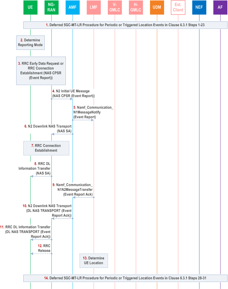
Figure 6.7.1-1 summarizes the initiation and reporting of location events for a deferred 5GC-MT-LR procedure for Periodic or Triggered Location Events using low power event reporting. This procedure is only applicable to a UE with E-UTRA access to 5GC.

Step 1.
Steps 1-23 for the deferred 5GC-MT-LR procedure for periodic or triggered location events in clause 6.3.1 are performed with the following exceptions.
Step 2.
-
At step 14, the AMF includes an indication in the Nlmf_
Location_ Request service operation that the UE supports and is allowed to use Control Plane CIoT 5GS Optimisation as described in clause 5.31.4 of TS 23.501.DetermineLocation - At step 16, if the AMF indicates the UE supports and is allowed to use Control Plane CIoT 5GS Optimisation at step 14 and if the LMF decides to allow Control Plane CIoT 5GS Optimisation, the LMF includes an indication in the LCS Periodic-Triggered Invoke Request that the UE is allowed to use Control Plane CIoT 5GS Optimisation to send Event Reports. The LMF may also include criteria indicating when Control Plane CIoT 5GS Optimisation may be used to send Event Reports. The criteria may include a maximum duration for sending Event Reports using Control Plane CIoT 5GS Optimisation, a maximum number of consecutive Event Reports to be sent using Control Plane CIoT 5GS Optimisation or both.
The UE determines whether to report the event detected at step 22 in clause 6.3.1 using Control Plane CIoT 5GS Optimisation or using a NAS signalling connection. If the UE is currently in CM CONNECTED state or is not accessing E-UTRA connected to 5GC, the UE shall use a NAS signalling connection. Otherwise, the determination shall be based on criteria received from the LMF at step 14 in clause 6.3.1 when criteria are received. When the criteria include a maximum duration for sending event reports using Control Plane CIoT 5GS Optimisation, the UE shall report the event using a NAS signalling connection if the UE has not used a NAS signalling connection to report events during an immediately preceding time interval equal to the maximum duration. When the criteria include a maximum number of consecutive Event Reports to be sent using Control Plane CIoT 5GS Optimisation, the UE shall report the event using a NAS signalling connection if the UE has used Control Plane CIoT 5GS Optimisation to report each of the N previous events, where N equals the maximum number of consecutive Event Reports. In other cases, Control Plane CIoT 5GS Optimisation may be used to report the event if supported by the 3GPP access type. If use of a NAS signalling connection is determined, steps 24-31 for the procedure in clause 6.3.1 are performed and steps 3-11 below are skipped. If use of Control Plane CIoT 5GS Optimisation is determined, steps 3-11 below are performed.
Step 3.
If the UE and ng-eNB node both support EDT, the UE sends an RRCEarlyDataRequest message to the ng-eNB node and includes a NAS control plane service request.
Otherwise, the UE established an RRC connection with the ng-eNB node and sends the NAS control plane service request. The NAS control plane service request includes an event report message which includes the information described in step 25 in clause 6.3.1 (e.g. the type of event being reported and any location measurements or location estimate obtained at step 23 in clause 6.3.1). The control plane service request also includes the deferred routing identifier received in step 16 in clause 6.3.1. The UE also includes a NAS Release Assistance Indication (NAS RAI) in the NAS message. The NAS RAI indicates a single response is expected.
Step 4.
The ng-eNB node forwards the NAS message to the AMF in an N2 Initial UE message and includes an "EDT Session" indication if EDT was used at step 3.
Step 5.
The AMF checks the integrity of the NAS message and deciphers its contents. The AMF then invokes an Namf_Communication_N1MessageNotify service operation to forward the event report to either the serving LMF or any suitable LMF as described for step 25 for clause 6.3.1. The AMF includes an indication of Control Plane CIoT 5GS Optimisation in the service operation and the serving cell ID.
Step 6.
The AMF returns a NAS Service Accept to the ng-eNB node which is encapsulated in an N2 Downlink NAS Transport message.
Step 7.
If EDT was used at step 3, the ng-eNB node establishes an RRC connection to the UE.
Step 8.
The ng-eNB node sends an RRC DL Information Transfer message to the UE and includes the NAS Service Accept message received in step 6.
Step 9.
The LMF invokes an Namf_Communication_N1N2MessageTransfer operation to return an acknowledgment for the event report as described for step 26 for clause 6.3.1.
Step 10.
The AMF forwards the acknowledgment to the ng-eNB node in a NAS DL NAS Transport message which is encapsulated in an N2 Downlink NAS Transport message. The AMF also includes an "end indication" in the N2 message.
Step 11.
The ng-eNB node sends an RRC DL Information Transfer message to the UE and includes the NAS message received in step 10.
Step 12.
If the "end indication" was received in step 10, the ng-eNB node releases the RRC connection.
Step 13.
If a location estimate is needed for event reporting, the LMF determines the UE location using the location measurements and/or location estimate received in the event report at step 5 and/or the serving cell ID provided by the AMF at step 5.
Step 14.
Steps 28-31 for clause 6.3.1 are performed to send the event report to the external client or AF and to continue event detection at the UE.
6.7.2 Event Reporting with change of LMF p. 78
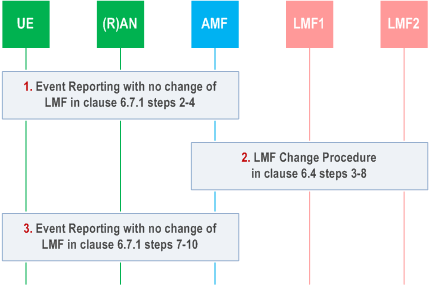
Figure 6.7.2-1 shows a procedure to enable change of the serving LMF when a UE sends an event report as at steps 3 and 4 in clause 6.7.1.

Precondition: Step 1 in clause 6.7.1 has already been performed and steps 2-11 in clause 6.7.1 may have been performed or repeated. A serving LMF is used and the current serving LMF is LMF1.
Step 1.
Steps 2-4 for Event Reporting for no change of LMF in clause 6.7.1 are performed with the following exceptions.
Step 2.
- At step 3, the NAS control plane service request includes a deferred routing identifier indicating LMF1.
Steps 3-8 for the LMF Change procedure in clause 6.4 are performed with the following exceptions.
Step 3.
-
At step 4, the Namf_
Communication_ service operation includes an indication of Control Plane CIoT 5GS Optimisation.N1MessageNotify -
At step 6, the Nlmf_
Location_ Request service operation includes an indication of Control Plane CIoT 5GS Optimisation and the serving cell ID.LocationContextTransfer
Steps 7-10 for Event Reporting for no change of LMF in clause 6.7.1 are performed with LMF2 replacing the LMF in clause 6.7.1. The rest of the procedure in clause 6.7.1 then continues in step 11 with LMF2 retaining state information to enable support of subsequent event reports from the UE.