Content for TS 23.259 Word version: 18.0.0
6 Procedures and information flows for PN redirection
6.1 Procedures and information flows in the IP CN subsystem
6.1.1 General
6.1.2 Procedures and information flows for PN UE redirection in the IM CN subsystem
6.1.3 Procedures and information flows for PNE redirection in the IM CN subsystem
...
...
6 Procedures and information flows for PN redirection p. 20
6.1 Procedures and information flows in the IP CN subsystem p. 20
6.1.1 General p. 20
One of the functionalities enabled by the PNM AS in the IM CN subsystem is called PNUE redirection that redirects sessions destined for any UEs of a PN to the default UE of the same PN as described in TS 22.259. The PN UE redirection applies only to the initial request for a UE-terminating call. The procedures for supporting the PN UE redirection in the IM CN subsystem take advantage of the interface between an S-CSCF and an AS in the IM CN subsystem described in TS 23.002 and the procedures described in TS 23.218.
When receiving an initial request for a UE-terminating call, the S-CSCF performs the procedure defined in TS 23.218 to route the initial request for the UE-terminating call to the PNM AS based on matching of initial filter criteria before performing any other routing procedures to the terminating UE. The PNM AS then executes the redirection of the initial request to the default UE of the PN based on the PN-user's PN configuration as described in clause 6. The redirection of the initial request for the UE-terminating call can be executed either on an IP multimedia application basis or on the media component(s) of an IP multimedia application basis supported by the terminating UE capabilities and the PN-user subscriptions.
If the PN-user configured a UE list of different priorities for the PN UE redirection, the PNM AS shall execute the session redirection for a particular UE based on the configuration in a decreasing order of the priority. If the session redirection for a UE of a higher priority fails, the PNM AS shall perform the PNM session redirection for the other UE of the next lower priority.
6.1.2 Procedures and information flows for PN UE redirection in the IM CN subsystem p. 20
Figure 6.1.2-1 describes the procedures and information flows for handling the PN UE redirection in the IM CN subsystem. Without loss of generality, it is assumed for Figure 6.1.2-1 that a PN-user's PN consists of two UEs, i.e., the UE-1 and the UE-2. The UE-2 is the default UE according to PN-user's PN configuration as described in clause 6. Furthermore, it is assumed that the two UEs have different public user identities.
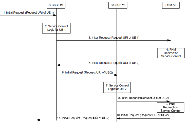
Figure 6.1.2-1: Initial request to UE-1 and redirected to UE-2 by the PNM AS in the IM CN subsystem
(⇒ copy of original 3GPP image)
(⇒ copy of original 3GPP image)
Step 1.
Figure 6.1.2-2 describes the procedures and information flows for handling the PN UE redirection in the IM CN subsystem when the default UE (in this example the UE-2) in the PN shares the same public user identity with the UE-1.
An initial request to the UE-1 containing the Request-URI of the UE-1 public user identity arrives at the S-CSCF #1.
Step 2.
The S-CSCF #1 determines that the initial request is for a UE-terminated case, invokes the termination service control logic required for the UE-1 and evaluates the initial filter criteria, which results in re-routing the initial request to the PNM AS.
Step 3.
As a result of the termination service control logic invocation for the UE-1, the S-CSCF #1 forwards the initial request to the PNM AS.
Step 4.
The PNM AS executes the PN UE redirection control logic based on the PN-user's PN configurations as described in clause 6. The PNM AS decides to redirect the initial request to the default UE of the PN, i.e., to the UE-2.
Step 5.
As a result of the PN UE redirection control logic execution, the PNM AS sends the redirected initial request containing the Request-URI of the UE-2 public user identity to the S-CSCF #1.
Step 6.
The S-CSCF #1 treats the redirected initial request as a UE-originated case, and forwards the redirected initial request to the S-CSCF #2. The S-CSCF #1 and the S-CSCF #2 can be the same entity.
Step 7.
The S-CSCF #2 treats the redirected initial request as a UE-terminated case, invokes the termination service control logic required for the UE-2 and evaluates the initial filter criteria, which may results in re-routing the redirected initial request to the other ASs.
Step 8-10.
The S-CSCF #2 forwards the redirected request to the PNM AS as the result of the termination service control logic for the UE-2. The PNM AS executes the PN UE redirection control logic and decides to forward the request as the UE-2 is the default UE of the PN.
Step 11.
The S-CSCF#2 continues the redirected initial request based on the standard call setup procedures as described in TS 23.228.
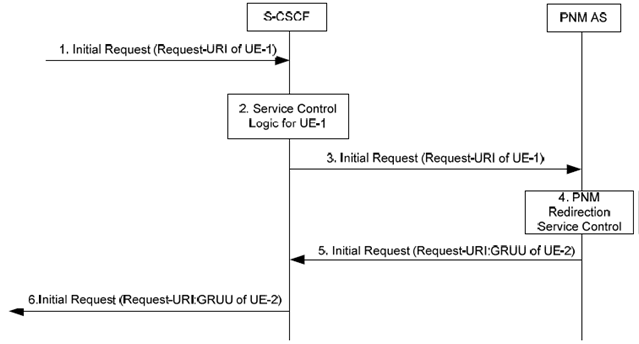
Figure 6.1.2-2: Initial request to UE-1 and redirected to UE-2 by the PNM AS in the IM CN subsystem when the UE-2 shares the same public user identity with the UE-1
(⇒ copy of original 3GPP image)
(⇒ copy of original 3GPP image)
Step 1.
Figure 6.1.2-3 describes the procedures and information flows for handling the PN UE redirection in the IM CN subsystem when the default UE (in this example the UE-2) in the PN cannot setup the session. Consequently, the PNM AS performs the PNM session redirection for the other UE of the next lower priority (in this example the UE-3).
An initial request to the UE-1 containing the Request-URI of the UE-1 public user identity arrives at the S-CSCF.
Step 2.
The S-CSCF determines that the initial request is for a UE-terminated case, invokes the termination service control logic required for the UE-1 and evaluates the initial filter criteria, which results in re-routing the initial request to the PNM AS.
Step 3.
As a result of the termination service control logic invocation for the UE-1, the S-CSCF forwards the initial request to the PNM AS.
Step 4.
The PNM AS executes the PNM redirection service control logic based on the User's PN configurations as described in clause 6. The PNM AS decides to redirect the initial request to the default UE of the PN, i.e., to the UE-2.
Step 5.
As a result of the PNM redirection service logic execution, the PNM AS sends the redirected initial request containing the Request-URI which is set to the GRUU of the UE-2 to the S-CSCF.
Step 6.
The S-CSCF continues the redirected initial request procedure based on the standard call setup procedures as described in TS 23.228.
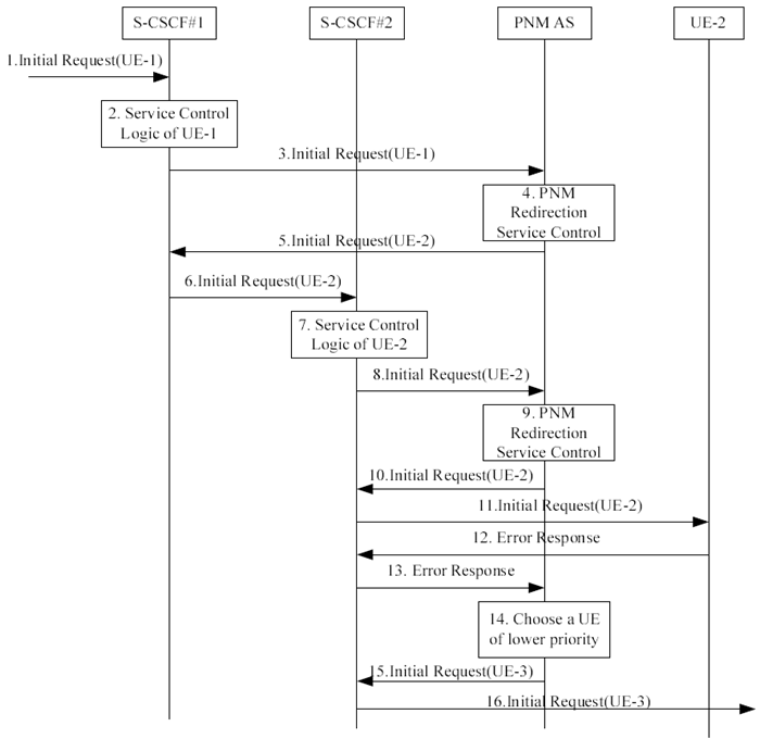
Figure 6.1.2-3: Initial request to UE-1 and redirected to UE-3 by the PNM AS in the IM CN subsystem when the initial request to UE-2 fails
(⇒ copy of original 3GPP image)
(⇒ copy of original 3GPP image)
Step 1.
An initial request to the UE-1 containing the Request-URI of the UE-1 public user identity arrives at the S-CSCF #1.
Step 2.
The S-CSCF #1 determines that the initial request is for a UE-terminated case, invokes the termination service control logic required for the UE-1 and evaluates the initial filter criteria, which results in re-routing the initial request to the PNM AS.
Step 3.
As a result of the termination service control logic invocation for the UE-1, the S-CSCF #1 forwards the initial request to the PNM AS.
Step 4.
The PNM AS executes the PN UE redirection control logic based on the PN-user's PN configurations as described in clause 6. The PNM AS decides to redirect the initial request to the default UE of the PN, i.e., to the UE-2.
Step 5.
As a result of the PN UE redirection control logic execution, the PNM AS sends the redirected initial request containing the Request-URI of the UE-2 public user identity to the S-CSCF #1.
Step 6.
The S-CSCF #1 treats the redirected initial request as a UE-originated case, and forwards the redirected initial request to the S-CSCF #2. The S-CSCF #1 and the S-CSCF #2 can be the same entity.
Step 7.
The S-CSCF #2 treats the redirected initial request as a UE-terminated case, invokes the termination service control logic required for the UE-2 and evaluates the initial filter criteria, which may results in re-routing the redirected initial request to the other ASs.
Step 8-10.
The S-CSCF #2 forwards the redirected request to the PNM AS as the result of the termination service control logic for the UE-2. The PNM AS executes the PN UE redirection control logic and decides to forward the request as the UE-2 is the default UE of the PN.
Step 11.
The S-CSCF#2 continues the redirected initial request which is forwarded to UE-2.
Step 12-13.
UE-2 cannot setup the session and returns an error response back to PNM AS.
Step 14.
The PNM AS executes the PN UE redirection control logic for the other UE of the next lower priority which in this example is UE-3.
Step 15-16.
As a result of the PN UE redirection control logic execution, the PNM AS forwards the redirected initial request containing the Request-URI of the UE-3 public user identity to the UE-3.
6.1.3 Procedures and information flows for PNE redirection in the IM CN subsystem |R9| p. 24
Figure 6.1.3-1 describes the procedures and information flows for handling the PNE redirection in the IM CN subsystem. Without loss of generality, it is assumed for Figure 6.1.3-1 that a PN-user's PN consists of three PNEs, i.e., the UE-1, the UE-2 and PNE-1.UE-2 and PNE-1 belong to a PAN. The PNE-1 is the default PNE according to PN-user's PN configuration as described in clause 6. Furthermore, it is assumed that the two UEs have different public user identities.
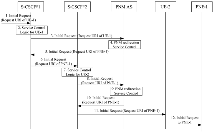
Figure 6.1.3-1: Initial request to UE-1 and redirected to PNE-1 by the PNM AS in the IM CN subsystem
(⇒ copy of original 3GPP image)
(⇒ copy of original 3GPP image)
Step 1.
An initial request to the UE-1 containing the Request-URI of the UE-1 public user identity arrives at the S-CSCF #1.
Step 2.
The S-CSCF #1 determines that the initial request is for a UE-terminated case, invokes the termination service control logic required for the UE-1 and evaluates the initial filter criteria, which results in re-routing the initial request to the PNM AS.
Step 3.
As a result of the termination service control logic invocation for the UE-1, the S-CSCF #1 forwards the initial request to the PNM AS.
Step 4.
The PNM AS executes the PNE redirection control logic based on the PN-user's PN configurations as described in clause 6. The PNM AS decides to redirect the initial request to the default UE of the PN, i.e., to the PNE-1.
Step 5.
As a result of the PNE redirection control logic execution, the PNM AS sends the redirected initial request containing the Request-URI of the GRUU of UE-2 and the identity of PNE-1 to the S-CSCF #1.
Step 6.
The S-CSCF #1 treats the redirected initial request as a UE-originated case, and forwards the redirected initial request to the S-CSCF #2. The S-CSCF #1 and the S-CSCF #2 can be the same entity.
Step 7.
The S-CSCF #2 treats the redirected initial request as a UE-terminated case, invokes the termination service control logic required for the UE-2 and evaluates the initial filter criteria, which can result in re-routing the redirected initial request to the other ASs.
Step 8-10.
The S-CSCF #2 forwards the redirected request to the PNM AS as the result of the termination service control logic for the UE-2. The PNM AS executes the PN UE redirection control logic and decides to forward the request as the PNE-1 is the default UE of the PN.
Step 11.
The S-CSCF#2 forwards the initial request including identity of PNE-1 to the UE-2.
Step 12.
The UE-2 forwards the initial request to the PNE-1 via the PAN internal interface.
![]()
![]()
![]()