Content for TS 23.259 Word version: 18.0.0
6.2 Procedures and information flows in the CS domain
6.3 Procedures and information flows in the domain interworking
6.3.1 General
6.3.2 Procedures and information flows for PN UE redirection from IM CN subsystem to CS domain
6.3.3 Procedures and information flows for PN UE redirection from CS domain to IM CN subsystem
...
...
6.2 Procedures and information flows in the CS domain p. 25
6.2.1 General p. 25
Similar to the functionality described in the subclause 6.1.1, the gsmSCF (CAMEL service for PNM) can redirect calls destined for any UEs of a PN in the CS domain to the default UE of the same PN. The procedures for supporting the PNM call redirection in the CS domain takes advantage of the interface between a GMSC and a gsmSCF in the CS domain described in TS 23.078 and the procedures described in TS 23.018.
When receiving a call request for a UE in the PN, the GMSC performs the procedure defined in TS 23.078 to route the request to the gsmSCF (CAMEL service for PNM) based on the T_CSI configured to the UE before performing any other routing procedures to the terminating UE. The gsmSCF (CAMEL service for PNM) then executes the redirection of the request based on the PN-user's PN configuration as described in clause 6.
If the PN-user configured a UE list of different priorities for the PNM call redirection, the gsmSCF (CAMEL service for PNM) shall execute the call redirection for a particular UE based on the configuration in a decreasing order of the priority. If the call redirection for a UE of a higher priority fails, the gsmSCF (CAMEL service for PNM) shall perform the PNM call redirection for the other UE of the next lower priority.
6.2.2 Procedures and information flows for PN UE redirection in the CS domain p. 25
Figure 6.2.2-1 describes the procedures and information flows for handling the PNM call redirection in the CS domain. Without loss of generality, it is assumed for Figure 6.2.2-1 that a PN-user's PN consists of two UEs, i.e., the UE-1 and the UE-2. The UE-2 is the default UE according to PN-user's PN configuration as described in clause 6.
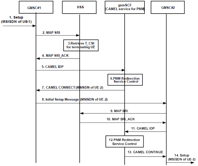
Figure 6.2.2-1: Initial request to UE-1 and redirected to UE-2 by the gsmSCF (CAMEL service for PNM) in the CS domain
(⇒ copy of original 3GPP image)
(⇒ copy of original 3GPP image)
Step 1.
Figure 6.2.2-2 describes the procedures and information flows for handling the PN UE redirection in the CS domain when the default UE (in this example the UE-2) in the PN cannot setup the session. Consequently, the gsmSCF performs the PNM session redirection for the other UE of the next lower priority (in this example the UE-3).
A call request to the UE-1 containing the MSISDN of the UE-1 as the called party number arrives at the GMSC #1.
Step 2.
On receipt of the incoming call request, the GMSC#1 queries the HSS for routing information.
Step 3.
The HSS provides information including the T-CSI information element that contains information configured for the PNM subscriber, identifying the subscriber as having terminating CAMEL services.
Step 4.
The HSS returns the T-CSI information element to the GMSC#1 in response to the query for routing information (SRI).
Step 5.
The GMSC#1 triggers a CAMEL activity which results in sending a CAMEL IDP message to the GSM Service Control Function (gsmSCF).
Step 6.
The gsmSCF (CAMEL service for PNM) executes the PN UE redirection control logic based on the PN-user's PN configurations as described in clause 6. The gsmSCF (CAMEL service for PNM) decides to redirect the call request to the default UE of the PN, i.e., to the UE-2.
Step 7.
As a result of the PN UE redirection control logic execution, the gsmSCF (CAMEL service for PNM) to respond to the CAMEL IDP message with a CAMEL CONNECT message containing the MSISDN of the UE-2 as the called party number.
Step 8.
The GMSC#1 initiates the CS call towards the GMSC#2 by sending an Initial Setup Message (e.g. ISUP IAM, BICC IAM, and SIP-I Invite).
Step 9-13.
The GMSC#2 queries the HSS for routing information and triggers a CAMEL activity to the gsmSCF. The gsmSCF executed the PNM redirection service control logic and decides to forward the request as the UE-2 is the default UE of the PN, so it responds with a CMAEL CONTINUE message to the GMSC#2.
Step 14.
The GMSC#2 continues the redirected call request based on the standard call setup procedures as described in TS 23.018.
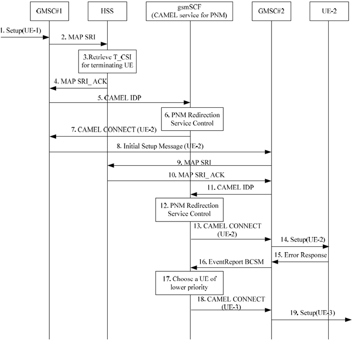
Figure 6.2.2-2: Initial request to UE-1 and redirected to UE-3 by the gsmSCF (CAMEL service for PNM) in the CS domain when the initial request to UE-2 fails
(⇒ copy of original 3GPP image)
(⇒ copy of original 3GPP image)
Step 1.
A call request to the UE-1 containing the MSISDN of the UE-1 as the called party number arrives at the GMSC #1.
Step 2.
On receipt of the incoming call request, the GMSC#1 queries the HSS for routing information.
Step 3.
The HSS provides information including the T-CSI information element that contains information configured for the PNM subscriber, identifying the subscriber as having terminating CAMEL services.
Step 4.
The HSS returns the T-CSI information element to the GMSC#1 in response to the query for routing information (SRI).
Step 5.
The GMSC#1 triggers a CAMEL activity which results in sending a CAMEL IDP message to the GSM Service Control Function (gsmSCF).
Step 6.
The gsmSCF (CAMEL service for PNM) executes the PN UE redirection control logic based on the PN-user's PN configurations as described in clause 6. The gsmSCF (CAMEL service for PNM) decides to redirect the call request to the default UE of the PN, i.e., to the UE-2.
Step 7.
As a result of the PN UE redirection control logic execution, the gsmSCF (CAMEL service for PNM) to respond to the CAMEL IDP message with a CAMEL CONNECT message containing the MSISDN of the UE-2 as the called party number.
Step 8.
The GMSC#1 initiates the CS call towards the GMSC#2 by sending an Initial Setup Message (e.g. ISUP IAM, BICC IAM, and SIP-I Invite).
Step 9-13.
The GMSC#2 queries the HSS for routing information and triggers a CAMEL activity to the gsmSCF. The gsmSCF executed the PNM redirection service control logic and decides to forward the request as the UE-2 is the default UE of the PN, so it responds with a CMAEL CONTINUE message to the GMSC#2.
Step 14.
The GMSC#2 continues the redirected call request based on the standard call setup procedures as described in TS 23.018.
Step 15.
UE-2 cannot setup the session and generates an error response.
Step 16.
GMSC#2 sends the EventReportBCSM message to the gsmSCF.
Step 17.
The gsmSCF executes the PN UE redirection control logic for the other UE of the next lower priority which in this example is UE-3.
Step 18-19.
As a result of the PN UE redirection control logic execution, the gsmSCF forwards the redirected initial request containing the MSISDN of the UE-3 as the called party number to the UE-3.
6.3 Procedures and information flows in the domain interworking p. 28
6.3.1 General p. 28
After the PNM AS executes the redirection of the initial request based on the PN-user's PN configuration, the initial request could be routed to different domain, i.e. from IM CN subsystem to CS domain or from CS domain to IM CN subsystem.
The procedures for supporting the interworking between IM CN subsystem and CS domain in the PNM session redirection take advantage of the procedures specified in TS 23.228.
6.3.2 Procedures and information flows for PN UE redirection from IM CN subsystem to CS domain p. 28
Figure 6.3.2-1 describes the procedures and information flows for handling the PNM Session redirection from IM CN subsystem to CS domain. Without loss of generality, it is assumed for Figure 6.3.2-1 that a PN-user's PN consists of two UEs, i.e., the UE-1 and UE-2 and the UE-2 attached in CS domain doesn't have the subscription to IMS is the default UE according to PN-user's PN configuration as described in clause 6.
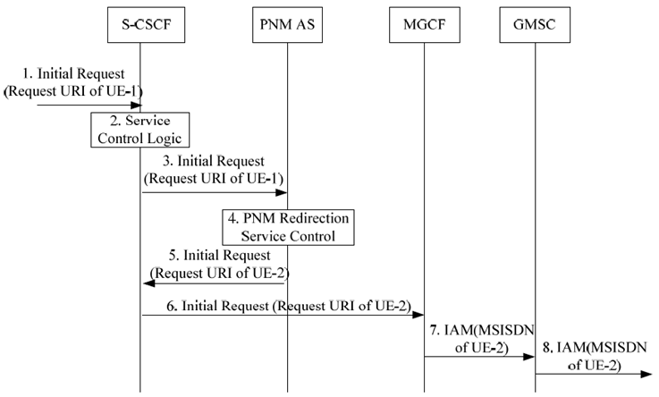
Figure 6.3.2-1: Initial request in IM CN subsystem and redirected to UE-2 in CS domain by the PNM AS
(⇒ copy of original 3GPP image)
(⇒ copy of original 3GPP image)
Step 1.
An initial request destined to the UE-1 containing the Request-URI of the UE-1 public user identity arrives at the S-CSCF.
Step 2.
The S-CSCF determines that the initial request if for a UE-terminated case, invokes the termination service control logic required for the UE-1 and evaluates the initial filter criteria, which results in re-routing the initial request to the PNM AS.
Step 3.
As a result of the termination service control logic invocation for the UE-1, the S-CSCF forwards the initial request to the PNM AS.
Step 4.
The PNM AS executes the PN UE redirection control logic based on the PN-user's PN configurations as described in clause 6. The PNM AS decides to redirect the initial request to the default UE of the PN, i.e., to the UE-2 which in this example can be found in the CS domain only.
Step 5.
As a result of the PN UE redirection control logic execution, the PNM AS sends the redirected initial request containing the Request-URI of the UE-2 public user identity to the S-CSCF.
Step 6.
The S-CSCF treats the redirected request as a UE-originated case and performs the domain transit procedure specified in TS 23.228. Eventually, the session initiation arrives to an MGCF.
Step 7.
The MGCF sends an IAM message containing the MSISDN of the UE-2 as the called party number towards GMSC.
Step 8.
The GMSC continues the redirected call request based on the standard call setup procedures as described in TS 23.018.
6.3.3 Procedures and information flows for PN UE redirection from CS domain to IM CN subsystem p. 29
Figure 6.3.3-1 describes the procedures and information flows for handling the PN UE redirection from CS domain to IM CN subsystem. Without loss of generality, it is assumed for Figure 6.3.3-1 that a PN-user's PN consists of two UEs, i.e., the UE-1 and UE-2 and the UE-2 registered only in IM CN subsystem is the default UE according to PN-user's PN configuration as described in clause 6.
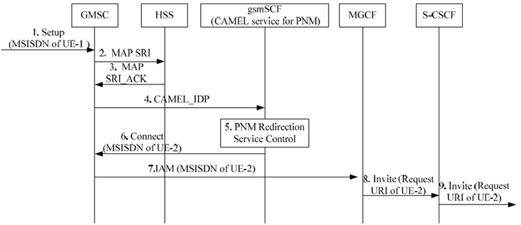
Figure 6.3.3-1: Initial request in CS domain and redirected to UE-2 in IM CN subsystem by the gsmSCF
(⇒ copy of original 3GPP image)
(⇒ copy of original 3GPP image)
Step 1.
A call request to the UE-1 containing the MSISDN of the UE-1 as the called party number arrives at the GMSC.
Step 2.
On receipt of the incoming call request, the GMSC queries the HSS for routing information.
Step 3.
The HSS returns the T-CSI information element that contains information configured for the PNM subscriber to the GMSC#1 in response to the query for routing information (SRI).
Step 4.
The GMSC triggers a CAMEL activity which results in sending a CAMEL IDP message to the gsmSCF (CAMEL service for PNM).
Step 5.
The gsmSCF (CAMEL service for PNM) executes the PN UE redirection control logic based on the PN-user's PN configurations as described in clause 6. The gsmSCF (CAMEL service for PNM) decides to redirect the call request to the default UE of the PN, i.e., to the UE-2 which in this example can be found in IM CN subsystem only.
Step 6.
As a result of the PN UE redirection control logic execution, the gsmSCF (CAMEL service for PNM) responds to the CAMEL IDP message with a CAMEL CONNECT message containing the MSISDN of the UE-2 as the called party number.
Step 7.
The GMSC initiates the call to the MGCF with an IAM message containing the MSISDN of UE-2 as the called party number.
Step 8.
The MGCF initiates a SIP INVITE request with the request URI of UE-2 public user identity towards the S-CSCF.
Step 9.
The S-CSCF continues the redirected initial request based on the standard call setup procedures as described in TS 23.228.
![]()
![]()
![]()