Content for TS 26.114 Word version: 18.6.0
0…
3…
4…
5…
6…
6.2.3…
6.2.5…
6.2.7…
6.2.10…
7…
7.5…
8…
9…
10…
10.2.1.6…
10.2.2…
10.3…
10.4…
11…
12…
12.3…
12.7…
13a…
16…
16.5…
17…
18…
19…
A…
A.3…
A.4…
A.5…
A.10…
A.14…
A.15…
B…
C…
C.1.3…
C.1.3.5
C.2…
D
E…
E.18…
E.31…
G…
K…
L…
M…
N…
O…
P…
P.3
Q…
R…
S…
T…
U…
V…
W…
X…
Y…
Y.6…
Y.6.4…
Y.6.5…
Y.7…
P Video packet loss handling operation principles and examples
P.1 General
P.2 Video error recovery
...
...
P Video packet loss handling operation principles and examples |R12| p. 408
P.1 General p. 408
This Annex describes operation principles and provides examples to video packet loss handling scheme described in clause 9.3. Several different video packet loss handling behaviours are possible at both sender and receiver ends for responding and reporting, respectively. Example criteria shown in this section are not to be seen as a scheme that excludes other designs. Implementers are free to use any packet loss algorithm as long as the requirements and recommendations specified in clause 9.3 are fulfilled.
P.2 Video error recovery p. 408
Efficient video error recovery requires error tracking capabilities at both the sender and the receiver side. Error detection and tracking is necessary on the receiver side for detecting the occurrence of the error as well as detecting the recovery from the error. On the sender side it is necessary for producing a recovery picture that would address the reported packet loss. Basically a receiver should be able to detect errors and report them to the sender in timely fashion. In return sender responds by sending recovery pictures or performing gradual decoder refresh (GDR).
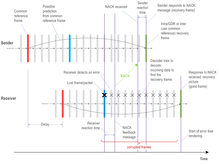
An example of video error recovery is illustrated in Figure P.1 below using a NACK message.

In this example, the error correction is performed in the following steps:
- Sender encodes a reference picture (blue) and transmits it. One or more of the packets belonging to this picture are lost.
- Receiver detects lost packets belonging to the blue picture upon receiving packets belonging to the picture following the blue picture or the last packet (if received) of the blue picture, after de-jittering.
- When the decoder tries to decode the picture following the blue picture and notices that a reference picture that it is referring to (i.e. the blue picture) is missing or has been partially received, and in response flags an error.
- Upon seeing the error report from the decoder, the receiver issues a NACK message. The duration of time that elapses from the first detection of missing packets to the issuance of the feedback message is denoted as the receiver reaction time.
- Sender receives the NACK message, feeds this information to the encoder, which responds by encoding the next picture either as an intra or inter picture. Alternatively the encoder can generate GDR over next N frames. In the inter-picture case, the encoder refers to a reference picture (red) that it assumes can be correctly decoded at the receiver side. The duration of time that elapses from receipt of the feedback message and sending of the recovery picture is denoted as the sender reaction time.
- Sender sends the recovery picture or the GDR to the receiver.
- Receiver's decoder continues to decode incoming pictures looking for the arrival of the recovery picture or full refresh from GDR. The receiver may opt not to render any incoming corrupted pictures while waiting for the arrival of the recovery picture or full refresh.

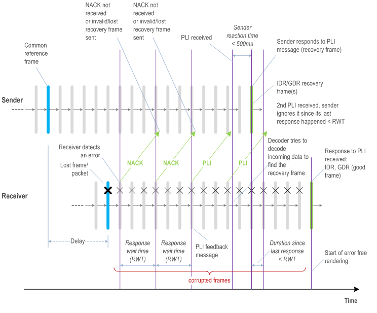
PLI request becomes necessary when the likelihood of having a common reference frame for inter error recovery is diminished. In this example, the error correction is performed in the following steps:
- Receiver issues a PLI message after waiting for two RWT duration for a recovery picture requested by NACK messages to arrive from the onset of the error.
- Sender upon reception of the PLI message, encodes the next picture as IDR picture or starts a GDR.
- Receiver receives the IDR picture or the GDR pictures resulting in full refresh.

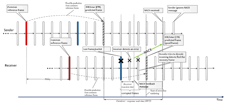
Figure P.3: Example case where sender does not have to respond to incoming NACK/PLI messages.
(⇒ copy of original 3GPP image)
(⇒ copy of original 3GPP image)
This case would apply to schemes where the sender periodically performs some form of periodic intra refresh or inter recovery (periodically predict from long term reference (LTR) pictures) as long as the period is conforms to the timing restrictions defined in clause 9.3.