Content for TS 26.114 Word version: 18.7.0
0…
3…
4…
5…
6…
6.2.3…
6.2.5…
6.2.7…
6.2.10…
7…
7.5…
8…
9…
10…
10.2.1.6…
10.2.2…
10.3…
10.4…
11…
12…
12.3…
12.7…
13a…
16…
16.5…
17…
18…
19…
A…
A.3…
A.4…
A.5…
A.10…
A.14…
A.15…
B…
C…
C.1.3…
C.1.3.5
C.2…
D
E…
E.18…
E.31…
G…
K…
L…
M…
N…
O…
P…
P.3
Q…
R…
S…
T…
U…
V…
W…
X…
Y…
Y.6…
Y.6.4…
Y.6.5…
Y.7…
9 Packet-loss handling
9.1 General
9.2 Speech
9.2.1 General
9.2.2 Transmitting redundant frames
9.2.3 Receiving redundant frames
9.3 Video
9.3.1 General
9.3.2 Receiver behaviour
9.3.3 Sender behaviour
9.3.4 Recommendations for packet loss recovery mechanisms usage
9.4 Text
...
...
9 Packet-loss handling p. 105
9.1 General p. 105
This clause specifies some methods to handle conditions with packet losses. Packet losses in general will also trigger adaptation, which is specified in clause 10.
The 'a=bw-info' attribute defined in clause 19 allows for negotiating how much additional bandwidth (if any) may be used for application layer redundancy in the session. When application layer redundancy is used, the media bandwidth negotiated for the session may need to be increased, i.e. by increasing the value used for the b=AS bandwidth modifier. The b=AS bandwidth modifier is however only a single value, which also applies only to the receiving direction. When an MTSI client in terminal sends the SDP, it is therefore not possible for the networks and the other client to know if the intention is to use the entire media bandwidth all the time (both with and without redundancy); or if the intention is to use the b=AS bandwidth only when redundancy is needed and to use a lower bandwidth when redundancy is not needed. It is also not possible to know what the MTSI client in terminal can do in the sending direction. The 'a=bw-info' attribute (see clause 19) offers an improved negotiation mechanism to better know what the MTSI client in terminal can do and what it intends to do. This is further discussed in TR 26.924.
Improved error robustness can be enabled by packet-loss handling procedures of the codec or codec mode, via the adaptation procedures described in clause 10, or other mechanisms. Annex X specifies the CHEM feature which enables the 3GPP system to exploit error robustness to avoid, delay, or reduce the need to handoff a terminal due to degradation in the media quality. Annex Y provides example PLR threshold values that can be used for different codec configurations.
9.2 Speech p. 105
9.2.1 General p. 105
This clause provides a recommendation for a simple application layer redundancy scheme that is useful in order to handle operational conditions with severe packet loss rates. Simple application layer redundancy is generated by encapsulating one or more previously transmitted speech frames into the same RTP packet as the current previously not transmitted frame(s). An RTP packet may thus contain zero, one or several redundant speech frames and zero, one or several non-redundant speech frames.
When transmitting redundancy, the MTSI client should switch to a lower codec mode, if possible. An MTSI client using AMR or AMR-WB shall utilize the codec mode rates within the negotiated codec mode set with the negotiated adaptation steps and limitations as defined by mode-change-neighbor and mode-change-period. It is recommended to not send redundant speech frames before the targeted codec mode is reached. Table 9.1 defines the recommended codec modes for different redundancy level combinations.
When application layer redundancy is used for AMR or AMR-WB encoded speech media, the transmitting application may use up to 300% redundancy, i.e. a speech frame transported in one RTP packet may be repeated in 3 other RTP packets.
| Redundancy level | No redundancy | 100% redundancy |
|---|---|---|
| Narrow-band speech | AMR 12.2 | AMR 5.9 |
| Wide-band speech (when wide-band is supported) | AMR12.65 | AMR 6.60 |
9.2.2 Transmitting redundant frames p. 105
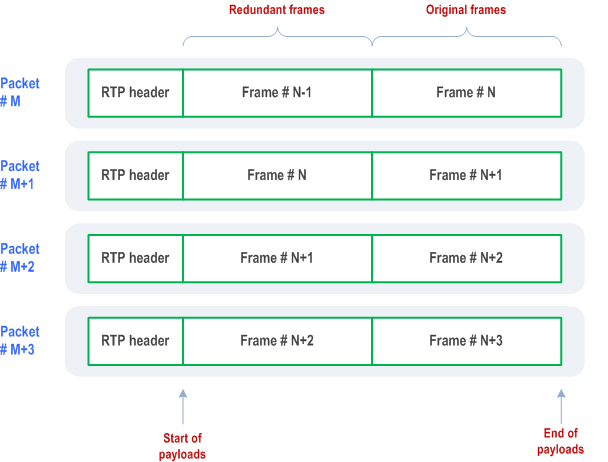
When transmitting redundant frames, the redundant frames should be encapsulated together with non-redundant media data as shown in Figure 9.1. The frames shall be consecutive with the oldest frame placed first in the packet and the most recent frame placed last in the packet. The RTP Timestamp shall represent the sampling time of the first sample in the oldest frame transmitted in the packet.

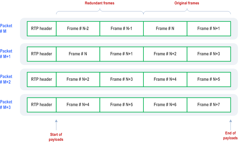
Figure 9.1 shows only one non-redundant frame encapsulated together with one redundant frame. It is allowed to encapsulate several non-redundant frames with one or several redundant frames. The following combinations of non-redundant frames and redundant frames can be used.
| Original encapsulation (without redundancy) | Encapsulation with 100% redundancy | Encapsulation with 200% redundancy | Encapsulation with 300% redundancy |
|---|---|---|---|
| 1 frame per packet | ≤ 1 non-redundant frame and
≤ 1 redundant frame | ≤ 1 non-redundant frame and
≤ 2 redundant frames | ≤ 1 non-redundant frame and
≤ 3 redundant frames |
| 2 frames per packet | ≤ 2 non-redundant frames and
≤ 2 redundant frames | ≤ 2 non-redundant frames and
≤ 4 redundant frames | ≤ 2 non-redundant frames and
≤ 6 redundant frames |
| 3 frames per packet | ≤ 3 non-redundant frames and
≤ 3 redundant frames | ≤ 3 non-redundant frames and
≤ 6 redundant frames | ≤ 3 non-redundant frames and
≤ 9 redundant frames |
| 4 frames per packet | ≤ 4 non-redundant frames and
≤ 4 redundant frames | ≤ 4 non-redundant frames and
≤ 8 redundant frames | Not allowed since maxptime does not allow more than 12 frames per RTP packet in this example |
With a maxptime value of 240, it is possible to encapsulate up to 12 frames per packet. It is therefore not allowed to use 300% when the original encapsulation is 4 frames per packet, as shown in Table 9.2. If the receiver's maxptime value is lower than 240 then even more combinations of original encapsulation and redundancy level will be prohibited.
The sender shall also ensure that the Maximum Transfer Unit (MTU) is not exceeded when sending the IP/UDP/RTP packet.
Figure 9.2 shows an example where the frame aggregation is 2 frames per packet and when 100% redundancy added.

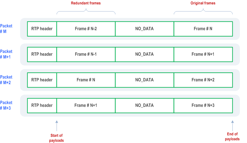
A redundant frame may be replaced by a NO_DATA frame. If the transmitter wants to encapsulate non-consecutive frames into one RTP packet, then NO_DATA frames shall be inserted for the frames that are not transmitted in order to create frames that are consecutive within the packet. This method is used when sending redundancy with an offset, see Figure 9.3.

Note that with this scheme, the receiver may receive a frame 3 times: first the non-redundant encoding; then as a NO_DATA frame; and finally the redundant frame. Other combinations of redundancy and offset may result in receiving even more copies of a frame. The proper receiver behaviour is described in the AMR/AMR-WB payload format (RFC 4867) and in the EVS payload format (TS 26.445), respectively.
For any combinations of frame aggregation, redundancy and redundancy offset, the transmitter shall not exceed the frame encapsulation limit indicated by the receiver's maxptime value when constructing the RTP packet.
When source controlled rate operation is used, it is allowed to send redundant media data without any non-redundant media, if no non-redundant media is available.
In the end of a talk spurt, when there are no more non-redundant frames to transmit, it is allowed to drop the redundant frames that are in the queue for transmission.
9.2.3 Receiving redundant frames p. 108
In order to receive and decode redundant media properly, the receiving application shall sort the received frames based on the RTP Timestamp and shall remove duplicated frames. If multiple versions of a frame are received, i.e. encoded with different bitrates, then the frame encoded with the highest bitrate should be used for decoding.
9.3 Video p. 109
9.3.1 General |R12| p. 109
MTSI clients can use the following mechanisms to recover from packet losses:
- AVPF Generic NACK and Picture Loss Indication (PLI) feedback messages
- RTP Retransmission
- Forward Error Correction (FEC)
9.3.2 Receiver behaviour |R12| p. 109
When NACK and PLI have been negotiated without retransmission support for the session then an MTSI client in terminal receiving media:
- shall immediately queue a NACK message for RTCP scheduling upon detection of first error after decoding a good frame.
- should repeat queuing NACK messages for RTCP scheduling after an RWT duration if recovery picture does not arrive.
- shall queue a PLI message for RTCP scheduling if a recovery picture does not arrive in two RWT duration, and shall then stop sending NACK messages that relate to the same data as that PLI.
- shall repeat queuing PLI messages for RTCP scheduling after an RWT duration if the initially requested recovery picture does not arrive.
9.3.3 Sender behaviour |R12| p. 109
When NACK and PLI have been negotiated without retransmission support for the session then an MTSI client in terminal sending media:
- shall send a recovery picture or Gradual Decoder Refresh (GDR) upon receiving NACK message if loss indicated by the message corresponds to error in a reference picture within 500 ms. If a recovery picture corresponding to the NACK message was sent prior to reception of the NACK message by less than RWT duration, the sender does not have to respond to this particular NACK message.
- shall send an Instantaneous Decoder Refresh (IDR) or GDR picture upon receiving PLI message within 500 ms.
- should not respond to incoming NACK or PLI messages within RWT duration of the same message type indicating the same loss from the reception of the initial feedback message triggered by the onset of the loss.
9.3.4 Recommendations for packet loss recovery mechanisms usage |R13| p. 110
FEC should be used to provide robustness against moderate packet loss rates at high delay scenario. FEC can especially handle random losses and short burst losses and be beneficial in environments with high packet loss rates and/or high delay (RTT). The use of FEC may not be appropriate when packet losses are caused by insufficient throughput (over radio access or due to congestions in network) since it introduces some bit rate overhead. In order to compensate for bit rate overhead, FEC should be used with efficient rate adaptation mechanisms to reduce the source bit rate according to channel conditions and not increase the total RTP bitrate. When error cases cannot be recovered by FEC, other mechanisms are needed in combination with FEC.
- Retransmission in combination with FEC should be used for the low RTT case with relatively high packet loss since retransmission can efficiently handle the FEC failure case.
- Generic NACK based recovery in combination with FEC should be used for high RTT, relatively high packet loss conditions since generic NACK based recovery does not introduce additional delay.
9.4 Text p. 111
Redundant transmission provided by the RTP payload format as described in RFC 4103 shall be supported. When the negotiation for support of multiparty real-time text is successful, redundant transmission provided by the RTP payload format as described in RFC 9071 shall also be supported. The transmitting application may use up to 200 % redundancy, i.e. a T140 block transported in one RTP packet may be repeated once or twice in subsequent RTP packets. 200 % redundancy shall be used when the conditions along the call path are not known to be free of loss. However, the result of media negotiation shall be followed, and transmission without redundancy used if one of the parties does not show capability for redundancy.
The sampling time shall be 300 ms as a minimum (in order to keep the bandwidth down) and should not be longer than 500 ms. New text after an idle period shall be sent as soon as possible. The first packet after an idle-period shall have the M-bit set.
The procedure described in Section 5 of RFC 4103, or a procedure with equivalent or better performance, shall be used for packet-loss handling in the receiving MTSI client in terminal.