Content for TS 26.114 Word version: 18.7.0
0…
3…
4…
5…
6…
6.2.3…
6.2.5…
6.2.7…
6.2.10…
7…
7.5…
8…
9…
10…
10.2.1.6…
10.2.2…
10.3…
10.4…
11…
12…
12.3…
12.7…
13a…
16…
16.5…
17…
18…
19…
A…
A.3…
A.4…
A.5…
A.10…
A.14…
A.15…
B…
C…
C.1.3…
C.1.3.5
C.2…
D
E…
E.18…
E.31…
G…
K…
L…
M…
N…
O…
P…
P.3
Q…
R…
S…
T…
U…
V…
W…
X…
Y…
Y.6…
Y.6.4…
Y.6.5…
Y.7…
C.1.3.5 Adaptation when using ECN |R9| p. 335
This example shows how ECN may be used to trigger media bit-rate adaptation. ECN can be used in combination with other adaptation triggers, for example packet loss triggered adaptation schemes or frame loss rate triggered adaptation schemes, although this is not included in this example.
In this example, the ECN-triggered adaptation is configured using the set of parameters as described in Table C.8.
| Parameter | Description |
|---|---|
| ECN_min_rate | Used in accordance with Table 10.1 |
| ECN_congestion_wait | Used in accordance with Table 10.1 |
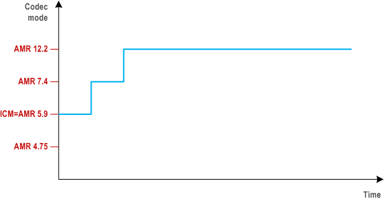
Figure C.5 shows how the codec rate changes over the session if there is no congestion and therefore no ECN-CE marking (and no packet losses). The codec modes that can be used during the session are negotiated at session setup. In this case it is assumed that the recommended four AMR {4.75, 5.9, 7.4 and 12.2 kbps} codec modes can be used in the session. It is further assumed that the highest codec mode allowed in the session is AMR 12.2 kbps and the ECN_min_rate corresponds to AMR 5.9 kbps, see clause 10.2.0.

The session starts with the Initial Codec Mode (ICM), i.e. the AMR 5.9 kbps codec mode, see clause 7.5.2.1.6. The receiving MTSI client evaluates the performance, for example by measuring the packet loss rate and detecting ECN-CE marked packets, and adapts the codec mode upwards (by sending adaptation requests backwards to the sender) in steps as long as no ECN-CE marked packets and no (or only marginal) performance problems are detected. In this case, this means that the MTSI client starts using the AMR 5.9 kbps mode, then switches to the AMR 7.4 kbps mode and then to the AMR 12.2 kbps mode.
The step-wise upswitching is used because the receiving MTSI client does not know whether the new and higher rate is sustainable or not. The transmission performance for each new rate needs to be verified over a time period before further upswitching can be attempted. If the new bit rate would prove to be not sustainable then the receiving MTSI client would switch back to the previously used rate or even a lower rate (not shown in these figures).
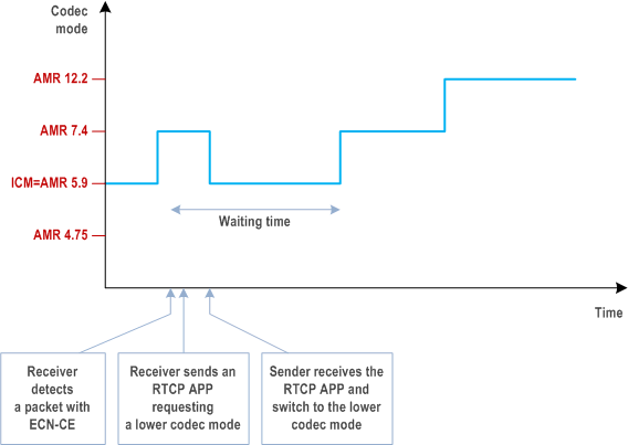
Figure C.6 shows how ECN-CE marked packets may trigger codec adaptation.

Again, the session starts with ICM, i.e. the AMR 5.9 kbps codec mode. The MTSI client evaluates the performance, for example the packet loss rate and/or ECN-CE marked packets, and adapts the codec mode upwards if it is deemed possible to do so. During the upwards adaptation, the receiver detects in this example a congestion event since ECN-CE is set for at least one of the received IP packets. In this case a fast back-off strategy is used and the receiver therefore sends an adaptation request back to the sender using RTCP APP with a request to switch to a low codec mode, in this case to adapt to the AMR 5.9 kbps mode. The AVPF profile allows for sending an (one) RTCP packet without waiting for the normal RTCP transmission interval, even if a regular compound RTCP was recently transmitted. This gives a faster reaction to ECN-CE.
After the down-switch, a waiting time is used to prevent upswitch too soon after the congestion event since too early upswitch is likely to trigger further congestion. The receiver uses RTCP APP also for the adaptation requests for upswitch. It is beneficial to use the normal RTCP transmission rules, defined for the AVP profile, for the upswitch adaptation signalling because this enables using the AVPF transmission rules in case congestion would occur immediately after the upswitch.
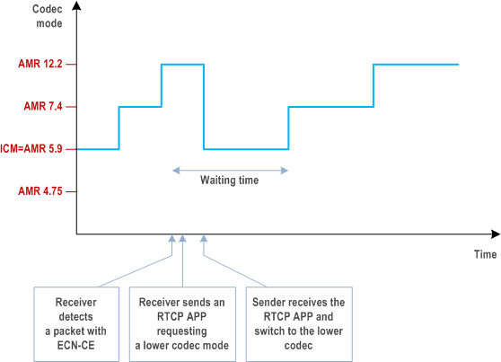
The response to the ECN-CE marking, the waiting time and the upswitching after a congestion event is the same regardless of when the congestion occurs, which is shown in Figure C.7. This is because the MTSI client is evaluating if the bit rate is sustainable also after switching up to the high bit rate.

Figure C.7 also shows how the fast down-switch gives a rapid codec mode switch from the AMR 12.2 kbps to the AMR 5.9 kbps mode. The codec mode request (CMR) sent from the receiver may suggest a direct switch from the AMR 12.2 kbps mode to the AMR 5.9 kbps mode. However, if the MTSI client is inter-working with a CS GERAN then mode changes will be limited in the session setup to every other frame border and also to neighboring modes. The MTSI client obviously has to follow such rules for mode changes, if they are defined in the session setup. The sender may therefore be prevented from following the CMR directly and it may take a few frames until the target codec mode is reached.