Content for TS 23.279 Word version: 17.0.0
A.3.3 Call flows for setting up the voice session for CSI origination and IMS termination with CSI interworking p. 31
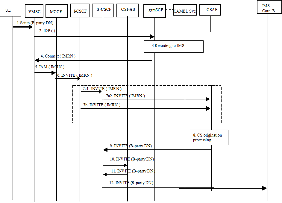
Figure A.3 shows the flows for establishing the voice session for CSI origination and IMS termination with the interworking performed in the originating network. The flow is simplified and omits elements such as I CSCF and HSS from IMS Core B.

Figure A.3: CSI interworking on originating side for CSI origination
(⇒ copy of original 3GPP image)
(⇒ copy of original 3GPP image)
Step 1.
The rest of the call is established as per normal SIP signalling with interworking towards the CS domain. The voice call is considered to be established.
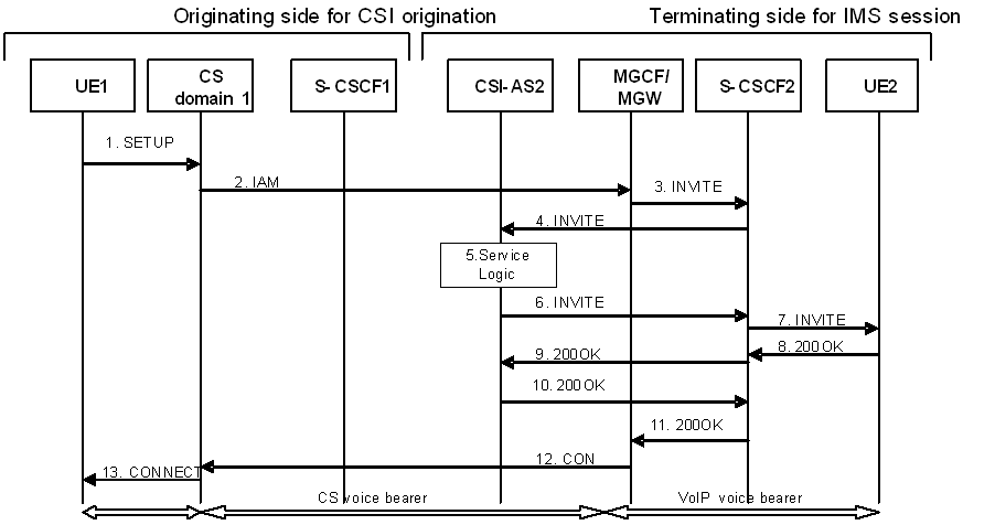
Figure A.4 shows the flows for establishing the voice session for CSI origination and IMS termination with the interworking performed in the terminating network. The flow is simplified and omits elements such as I CSCF and HSS.
The CSI user originates a voice call in the CS domain using a CSI UE to party B.
Step 2.
Origination triggers at the VMSC are detected; VMSC sends an Initial DP message towards the gsmSCF.
Step 3.
The gsmSCF invokes the CSI interworking Application's CAMEL Service that determines that the call needs to be interworked to IMS for CSI; thus, the CAMEL Service interworks the call to the IMS by allocating an IMRN and returning it to the gsmSCF; otherwise it responds with a CAP Continue.
Step 4.
The gsmSCF responds with a CAP Connect message containing the Original Called party ID and Destination Routing Address. Destination Routing Address contains the IMRN to route the call to the CSAF. Handling of Destination Routing Address and Original Called party ID is as defined in TS 23.078.
Step 5.
The VMSC routes the call towards the user's home IMS network using the IMRN via an MGCF in the home network.
Step 6.
The MGCF initiates an INVITE towards the I-CSCF in the home IMS of the originating CSI user. The calling party number and/or original called number are included in the INVITE if they are received from the PSTN call setup signalling (e.g. ISUP).
Step 7.
The I CSCF routes the INVITE based on one of the following standard procedures specified in "PSI based Application Server termination - direct" and "PSI based Application Server termination - indirect" procedures in TS 23.228.
Step 7a.
The I CSCF forwards the INVITE to the CSAF via the S CSCF that is assigned to the IMRN.
Step 7b.
The I CSCF forwards the INVITE directly to the CSAF.
Step 8.
If, when the INVITE arrives at the CSI Interworking Application, it is processed by the CSAF of the CSI Interworking Application that may use the IMRN to retrieve the original called party number and the calling party number from the CAMEL Service. The CSAF uses the original called number and the calling party number to setup the outgoing call leg to party B in accordance with the AS origination procedure defined in clause 5.6.5 of TS 23.228.
Step 9.
The CSAF sends the INVITE back to the S CSCF for completion of the call toward the remote end.
Step 10.
The S CSCF forwards the INVITE to the CSI AS
Step 11.
The CSI AS forwards the INVITE to the S CSCF.
Step 12.
The CSI AS forwards the INVITE to the IMS Core B.

Figure A.4: CSI interworking on terminating side for CSI origination
(⇒ copy of original 3GPP image)
(⇒ copy of original 3GPP image)
Step 1.
The voice bearer is considered to be established.
UE1 initiates a voice call on the CS side by sending a SETUP message to the CS domain (MSC).
Step 2.
The originating network generates an IAM which is forwarded to the visiting network. The IAM is routed to a MGCF.
Step 3.
The MGCF generates an INVITE and forwards the INVITE the call to S CSCF2.
Step 4.
S CSCF2, based upon iFC, forwards the INVITE to CSI AS2.
Step 5.
CSI AS2 terminates the INVITE from the MGCF and generates a new INVITE towards UE2. It also performs the service logic required for originating CSI interworking (e.g. 3rd party call control).
Step 6.
CSI AS2 sends the INVITE back towards S CSCF2.
Step 7.
S CSCF2 forwards the INVITE to UE2.
Step 8.
UE2 accepts the session by responding to S CSCF2 with a 200OK.
Step 9.
S CSCF2 forwards the 200 OK to CSI AS2.
Step 10.
CSI AS2 forwards the 200OK back to S CSCF2.
Step 11.
S CSCF2 forwards the200OK to the MGCF.
Step 12.
The MGCF generates a CON messages which is sent to the originating CS domain.
Step 13.
The MSC in the CS domain accepts the call by sending a CONNECT to UE1.