Content for TS 23.279 Word version: 18.0.0
A Support of CSI origination towards IMS termination with CSI interworking
A.1 Introduction
A.2 Overview
A.3 Procedures
A.3.1 General Architecture
...
...
A Support of CSI origination towards IMS termination with CSI interworking p. 29
A.1 Introduction p. 29
This Annex describes the flows and architecture for CSI originations towards IMS termination with CSI interworking.
CSI interworking is the ability to perform the interworking between e.g. a pure IMS voice/video session and a combination of a CS call and an IMS session.
A.2 Overview p. 29
CSI interworking from CSI origination to IMS termination is required to enable communication from UE's support CSI towards UEs supporting IMS termination. CSI interworking can be implemented in two different ways:
- CSI interworking can also be achieved in the terminating terminal if the operator has control of the terminal. This is beyond the scope of this document.
- CSI Interworking is detected and performed in the originating network.
- CSI Interworking is detected and performed in the terminating network.
A.3 Procedures p. 29
A.3.1 General Architecture p. 29
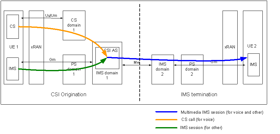
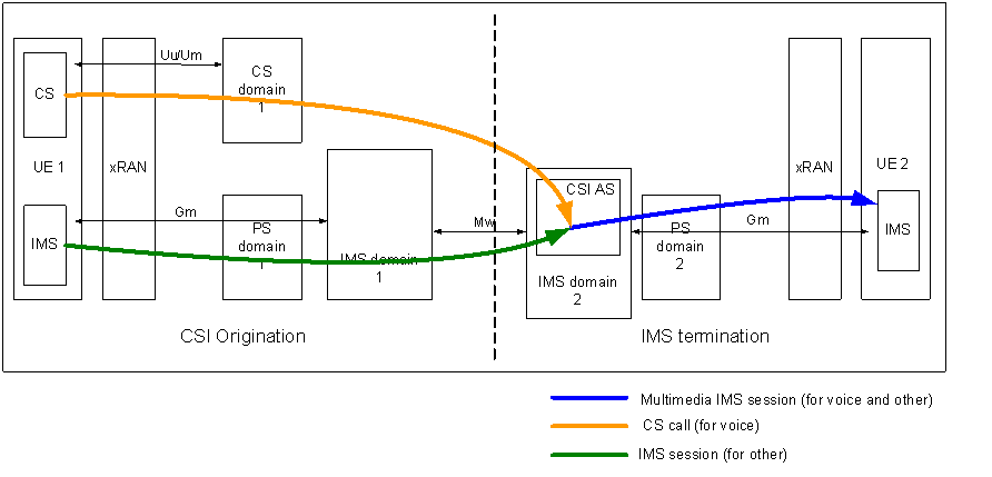
Figure A.1 and Figure A.2 show an architecture for the general architecture for CSI interworking when CSI origination and IMS termination is used for the CSI interworking with the support of interworking in the network. Figure A.1 shows the case where the CSI interworking is performed in the originating network, and Figure A.2 shows the case where the CSI interworking is performed in the terminating network.

Figure A.1: General architecture and signalling flow in case of CSI origination and IMS termination with CSI interworking in originating network
(⇒ copy of original 3GPP image)
(⇒ copy of original 3GPP image)

Figure A.2: General architecture and signalling flow in case of CSI origination and IMS termination with CSI level interworking in terminating network
(⇒ copy of original 3GPP image)
(⇒ copy of original 3GPP image)
The solid lines present the signalling flow between UE 1 and UE 2. The voice call (yellow line) which is initiated by UE 1 is routed to the CSI AS, while the IMS session for other services is also routed to the CSI AS. The CSI AS continues the communication towards UE 2 with a single session using normal IMS routing procedure. The above examples illustrate the interworking in both originating and the terminating networks and further consideration is required in order to determine whether the CSI AS is in the originating network, terminating network or both.