Content for TS 23.003 Word version: 18.6.0
1…
2…
2.8…
3…
4…
5…
6…
7…
8…
9…
10…
11
12…
13…
14…
15…
16…
17…
18…
19…
19.4…
19.5…
20…
21…
22…
23…
24…
25…
26…
27…
28…
28.3.2.2…
28.3.2.2.6…
28.3.2.3…
28.4…
28.7…
28.8…
29…
A…
B…
C…
D
E…
29 Numbering, addressing and identification for RACS
29.1 Introduction
29.2 UE radio capability ID
30 Identification of 5GS Multicast and Broadcast Services
30.1 Introduction
30.2 Structure of TMGI
30.3 Structure of Area Session ID
30.4 Structure of MBS Frequency Selection Area ID
30.5 Structure of Associated Session ID
...
...
29 Numbering, addressing and identification for RACS |R16| p. 140
29.1 Introduction p. 140
This clause describes the format of the parameters used for Radio Capability Signalling Optimisation (RACS). For further information on the use of the parameters see TS 23.401 and TS 23.501.
29.2 UE radio capability ID p. 141
The UE radio capability ID is an identifier used to represent a set of UE radio capabilities, defined in TS 23.501 and in TS 23.401, composed as shown in Figure 29.2-1.

The UE radio capability ID is composed of the following elements (each element shall consist of hexadecimal digits only):
-
Type Field (TF): identifies the type of UE radio capability ID. The following values are defined:
- 0: manufacturer-assigned UE radio capability ID;
- 1: network-assigned UE radio capability ID; and
- 2 to F: spare values for future use.
-
The Vendor ID is an identifier of UE manufacturer. This is defined by a value of Private Enterprise Number issued by Internet Assigned Numbers Authority (IANA) in its capacity as the private enterprise number administrator, as maintained at https://
www. . Its length is 8 hexadecimal digits. This field is present only if the Type Field is set to 0;iana. org/ assignments/ enterprise-numbers/ enterprise-numbers - The Version ID is the current Version ID configured in the UCMF. This field is present only if the Type Field is set to 1. Its length is 2 hexadecimal digits.
- Radio Configuration Identifier (RCI): identifies the UE radio configuration. Its length is 11 hexadecimal digits.
30 Identification of 5GS Multicast and Broadcast Services |R17| p. 141
30.1 Introduction p. 141
This clause describes the format of the parameters needed to access the Multicast and Broadcast Services in 5GS. For further information on the use of the parameters see TS 23.247.
30.2 Structure of TMGI p. 142
Temporary Mobile Group Identity (TMGI) is used within MBS to uniquely identify a broadcast MBS session or a multicast MBS session.
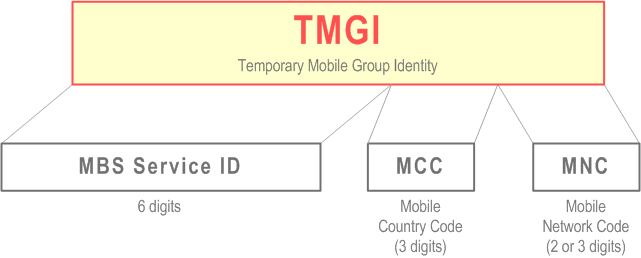
TMGI is composed as shown in Figure 30.2.1.

The TMGI is composed of three parts:
- MBS Service ID consisting of three octets. MBS Service ID consists of a 6-digit fixed-length hexadecimal number between 000000 and FFFFFF. MBS Service ID uniquely identifies an MBS service within a PLMN.
- Mobile Country Code (MCC) consisting of three digits. The MCC identifies uniquely the country of domicile of the MB-SMF, except for the MCC value of 901, which does not identify any country and is assigned globally by ITU;
- Mobile Network Code (MNC) consisting of two or three digits (depending on the assignment to the PLMN by its national numbering plan administrator). The MNC identifies the PLMN which the MB-SMF belongs to, except for the MNC value of 56 when the MCC value is 901, which does not identify any PLMN. For more information on the use of the TMGI, see TS 23.247.
30.3 Structure of Area Session ID p. 142
The concept of Area Session ID is defined in TS 23.247.
Area Session IDs are used for MBS sessions with location dependent content. An Area Session ID together with an MBS Session ID (i.e. TMGI or Source Specific IP Multicast address) shall uniquely identify an MBS session in a specific MBS Service Area.
An Area Session Identity shall be a decimal number between 0 and 65535 (inclusive).
30.4 Structure of MBS Frequency Selection Area ID p. 142
The concept of MBS Frequency Selection Area ID is defined in clause 6.5.4 of TS 23.247.
The MBS Frequency Selection Area (FSA) ID is used for broadcast MBS session to guide the frequency selection of the UE.
The MBS FSA ID identifies a preconfigured area within, and in proximity to, which the cell(s) announces the MBS FSA ID and the associating frequency (for details see TS 38.300). MBS FSA ID and their mapping to frequencies are provided to RAN nodes via OAM.
An MBS FSA ID shall be a string of 6 hexadecimal digits.
30.5 Structure of Associated Session ID |R18| p. 143
The concept of Associated Session ID is defined in TS 23.247.
The Associated Session ID is used to enable NG-RAN to identify the multiple MBS sessions delivering the same content when AF creates multiple broadcast MBS Sessions via different Core Networks in network sharing scenarios.
An Associated Session ID may comprise a Source Specific IP Multicast Address (SSM) or a string. See clause 5.9.4.21.1 of TS 29.571 for the encoding of Associated Session ID in 5GC SBIs.