| |
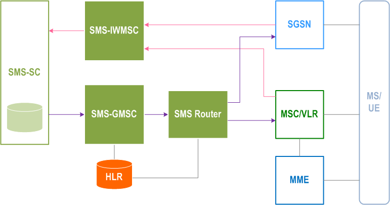
Figure 1 | The Short Message Service mobile terminated |
Figure 2 | The Short Message Service mobile originated |
Figure 3 | Example of how information on one MS can be put in relation to SC(s) in order to fulfil the requirement of Alert-SC mechanism |
Figure 3a | Structure of the MT Correlation ID |
Table 1 | Error indications related to mobile terminated short message transfer which may be transferred to the originating SC |
Table 1a | Assignment of values to reasons for absence (values must be in the range of 0 to 255, see 3GPP TS 29.002 [15]) |
Figure 4 | Entities involved in the provision of SM MT and SM MO |
Figure 5 | The main network structure serving as a basis for the short message transfer |
Figure 6 | Reference configuration of the MS which apply to the SMS |
Figure 7 | Protocol layer overview for the Short Message Service |
Figure 8 | 21 bits from the octets 5, 6, 7, and 8 in a short message α) shall represent an integer as shown in β), and shall be transmitted in an order as shown in Γ) |
Figure 9.1.2.3-1 | Example of Semi-octet representation |
Figure 9.1.2.5-1 | Address field format |
Figure 9.1.2.5-2 | Type-of-Address field format |
Table 9.2.2.1-1 | Basic elements of the SMS-DELIVER type |
Figure 9.2.2.1-1 | Layout of SMS-DELIVER |
Table 9.2.2.1a-1 | Basic elements of the SMS-DELIVER-REPORT type for RP-ERROR |
Figure 9.2.2.1a-1 | Layout of SMS-DELIVER-REPORT for RP-ERROR |
Table 9.2.2.1a-2 | Basic elements of the SMS-DELIVER-REPORT type for RP-ACK |
Figure 9.2.2.1a-2 | Layout of SMS-DELIVER-REPORT for RP-ACK |
Table 9.2.2.2-1 | Basic elements of the SMS-SUBMIT type |
Figure 9.2.2.2-1 | Layout of SMS-SUBMIT |
Table 9.2.2.2a-1 | Basic elements of the SMS-SUBMIT-REPORT type for RP-ERROR |
Figure 9.2.2.2a-1 | Layout of SMS-SUBMIT-REPORT for RP-ERROR |
Table 9.2.2.2a-2 | Basic elements of the SMS-SUBMIT_REPORT type for RP-ACK |
Figure 9.2.2.2a-2 | Layout of SMS-SUBMIT-REPORT for RP-ACK |
Table 9.2.2.3-1 | Basic elements of the SMS-STATUS-REPORT type |
Figure 9.2.2.3-1 | Layout of SMS-STATUS-REPORT |
Table 9.2.2.4-1 | Basic elements of the SMS-COMMAND type |
Figure 9.2.2.4-1 | Layout of SMS-COMMAND |
Table 9.2.3.11-1 | |
Table 9.2.3.19-1 | |
Table 9.2.3.22-1 | |
Figure 9.2.3.24-a | |
Figure 9.2.3.24-b | |
Figure 9.2.3.24-c | |
Figure 9.2.3.24.1-a | Concatenation of a Compressed short message |
Figure 9.2.3.24.10.1.13 | |
Figure 9.2.3.24.10.1.15 | |
Figure 9.2.3.24.10.1.15.1.a | LZSS compressed data format |
Figure 9.2.3.24.10.1.15.1.b | Literal block identifier |
Figure 9.2.3.24.10.1.15.1.c | Slice Descriptor |
Figure 9.2.3.24.11-a | |
Figure 9.2.3.24.11-b | |
Figure 9.2.3.24.11-c | |
Table 9.2.3.24.13.1-1 | |
Table 9.2.3.24.13.2-1 | |
Figure 14 | Interfaces involved in the Short message mobile terminated procedure. GSM TS 43.002 [5]. X is the interface between an MSC and an SC as defined in clause 5 |
Figure 15a | Successful short message transfer attempt via the MSC or the SGSN |
Figure 15aa | Successful short message transfer attempt via the SMS Router, and the MSC or SGSN |
Figure 15b | Short message transfer attempt failing due to error at the SMS-GMSC |
Figure 15c | Short message transfer attempt failing due to negative outcome of HLR information retrieval |
Figure 15ca | Short message transfer attempt via the SMS Router failing due to negative outcome of HLR information retrieval |
Figure 15d | Short message transfer attempt failing due to error at the MSC or SGSN |
Figure 15e | Short message transfer attempt failing due to negative outcome of VLR information retrieval |
Figure 15f | Short message transfer attempt failing due to erroneous message transfer on the radio path |
Figure 15g | Short message transfer attempt failing over the first path (e.g. SGSN) and succeeding over the second path (e.g. MSC) |
Figure 15ga | Short message transfer attempt via the SMS Router failing over the first path (e.g. SGSN) and succeeding over the second path (e.g. MSC) |
Figure 15h | Short message transfer attempt failing over the first path (e.g. SGSN) and over the second path (e.g. MSC) |
Figure 16a | "Send information for MT SMS" procedure; error free case |
Figure 16b | "Send information for MT SMS" procedure; erroneous case: absent subscriber (e.g. IMSI DETACH or GPRS DETACH) |
Figure 16c | "Send information for MT SMS" procedure; erroneous case: Absent subscriber (e.g. no paging response) |
Figure 16d | "Send information for MT SMS" procedure; incorrect authentication |
Figure 17a | Successful short message transfer attempt via the MSC, SGSN or MME, with short message retransmission by the SMS-GMSC at the time requested by the MSC, SGSN or MME |
Figure 17b | Successful short message transfer attempt via the MSC, SGSN or MME, with short message retransmission by the SMS-GMSC upon MS originated signalling prior to the retransmission time requested by the MSC, SGSN or MME |
Figure 17c | Successful short message transfer attempt via the MSC, SGSN or MME, with short message retransmission by the SMS-GMSC upon MS mobility to a new serving node prior to the retransmission time requested by the MSC, SGSN or MME. |
Figure 17 | Interfaces involved in the Short message mobile originated procedure GSM TS 43.002 [5]. X is the interface between an MSC or an SGSN and an SC as defined in clause 5. |
Figure 18a | Successful short message transfer attempt |
Figure 18b | Short message transfer attempt failing due to error at the MSC or SGSN |
Figure 18c | Short message transfer attempt failing due to negative outcome of VLR information retrieval |
Figure 18d | Short message transfer attempt failing due to error at the SMS-IWMSC |
Figure 18e | Short message transfer attempt failing due to error at the SC |
Figure 18f | Short Message transfer Successful due to the existence of an SMS Interworking agreement |
Figure 18g | Short Message transfer attempt failing due to non-existence of an SMS Interworking agreement |
Figure 18h | Short Message transfer attempt failing due to negative outcome of HLR information retrieval |
Table 10.2-1 | |
Figure 19 | Interfaces involved in the Alert procedure. X is the interface between an SC and an MSC as defined in clause 5 |
Figure 20a | The alert procedure when the MS becomes reachable, MNRF, MNRG or both are set and MCEF is not set |
Figure 20b | The alert procedure when the MS becomes reachable, MNRF, MNRG or both are set and MCEF is set |
Figure 20c | The alert procedure when the MS notifies the network that it has memory available to receive one or more short messages and MCEF is set |
Table 11.1-1 | |
Table 11.2-1 | |
Table 11.3-1 | |
Table 11.3-2 | |
Figure C.1 | Mobile terminated short message |
Figure C.2 | Mobile terminated short message |
Figure C.3 | Mobile terminated short message |
Figure C.4 | Mobile terminated short message |
Figure C.5 | Acknowledgement in the MT case |
Figure C.6 | Acknowledgement in the MT case |
Figure C.7 | Acknowledgement in the MT case |
Figure C.8 | Acknowledgement in the MT case |
Figure C.9 | Mobile originated short message |
Figure C.10 | Mobile originated short message |
Figure C.11 | Mobile originated short message |
Figure C.12 | Mobile originated short message |
Figure C.13 | Acknowledgement in the MO case |
Figure C.14 | Acknowledgement in the MO case |
Figure C.15 | Acknowledgement in the MO case |
Figure C.16 | Acknowledgement in the MO case |
Figure F.1 | Illustration of "Implicit Dictionary" compression methods |
Figure F.2 | Sample input buffer (16 octets long) |
Figure F.3 | Output buffer after initial literal block is written |
Figure F.4 | Output buffer after the first slice descriptor is written |
Figure F.5 | Second literal block is written into output buffer |
Figure F.6 | Octet match slice descriptor is written into output buffer |
Figure F.7 | Octet match slice descriptor is written into output buffer: the final output buffer |
Figure G.1.3.1-1 | |
Figure G.1.3.1-2 | |
Figure G.1.3.2-1 | |
Figure G.2.1.2-1 | |
Figure G.2.1.4-1 | |
Figure G.2.3.2-1 | |
Figure G.2.4-1 | |
Figure G.2.4-2 | |
Table I.1 | Mapping between architecture and reference points for SMS in MME and the present specification |
Table J.1 | Mapping between architecture and reference points for SMS over SGSN using Diameter interface and the present specification |
Table K.1 | Mapping between architecture and reference points for SMS in 5GS and the present specification |