Content for TR 22.859 Word version: 18.2.0
A Connectivity models
A.1 General
A.2 PIN direct connectivity with no relay
A.3 PIN direct connection using a relay
$ Change history
A Connectivity models p. 49
A.1 General p. 49
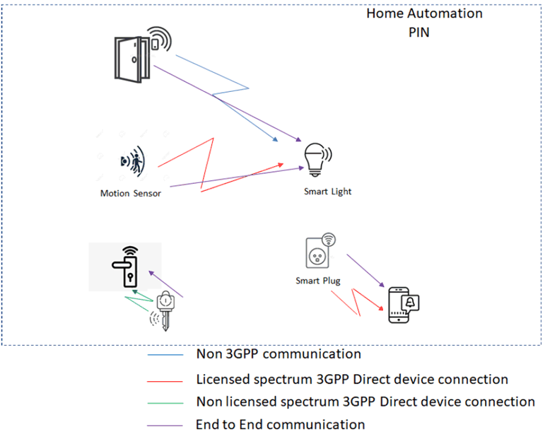
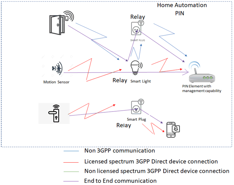
This annex provides a diagrammatic view of the types of connectivity models that are supported in a PIN. Each diagram will contain 2 types of lines, one that shows a PIN Element to PIN Element transport and a second line that shows the end to end communication. In both diagrams PIN Elements use PIN direct connections, however PIN Element to PIN Element end to end communication may require a relay.
A PIN Element may support more than one form of connectivity but this is not shown in the diagrams.
A.2 PIN direct connectivity with no relay p. 49

Figure A2-1 shows PIN Elements that communicate directly, without any relay elements to another PIN Element, this is collectively known as PIN direct connection. PIN direct connection can encompass different types of direct connection as show in Figure A2-1:
- Door sensor (a device PIN Element) uses PIN direct connection (e.g. WLAN) to communicate with a light bulb (e.g. door opens and the light turns on).
- Motion sensor (UE PIN Element) uses PIN direct connection in licensed spectrum to communicate with the light bulb (e.g. motion is detected in the room and the light bulb turns on).
- The key uses PIN direct connection in non licensed spectrum to communicate with the door lock (e.g. key opens the door).
- The smart plug (UE PIN Element) uses PIN direct connection in licensed spectrum to communicate with the smartphone (e.g. notification that it is using 60 watts of energy).
A.3 PIN direct connection using a relay p. 50

Figure A3-1 shows PIN Elements that communicate directly but there is a relay in the communication path. Figure A3-1 shows the following:
- Door sensor (device PIN Element) uses PIN direct connection (Non 3GPP communication) to communicate with a PIN Element with management capability via 2 relays (light bulb and smart switch).
- Motion sensor (UE PIN Element) uses PIN direct connection in licensed spectrum to communicate with the a PIN Element with management capability via a relays (light bulb) (e.g. to configure the motion sensor to turn the light bulb on or off).
- The door lock (UE PIN Element) uses PIN direct connection in licensed spectrum to communicate with the smartphone (e.g. notification that it opened) via a relay (smart socket).