Content for TR 22.839 Word version: 18.1.0
5.12 Optimizing UE mobility from planned or predicted mobility information
5.13 Use of mobile relay as secondary node
...
...
5.12 Optimizing UE mobility from planned or predicted mobility information p. 33
5.12.1 Description p. 33
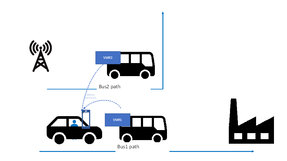
Urban buses of a city are equipped with a mobile base station relay i.e. Vehicle-mounted Relays (VMRs).
The city provides also autonomous cars rental for moving in the centre or in the suburb of the city. Autonomous cars of the city may follow the same corridors as the city buses.
Each autonomous car is equipped with a built-in UE and a roof antenna.
Bob is going to work. Bob hires one autonomous car and configures the path to go to his work office in the car.
Along the path to the work office, the autonomous car's UE can connect to different fixed base stations or mobile base station relays providing a better signal quality for a short period, thereby triggering a large number of handovers. This can be inefficient, since it is preferred that his car's UE selects a fixed base station or a mobile base station relay that provides good connectivity for a longer duration.
To minimize the number of handovers and to provide a service continuity, the 5G system can predict the usual itinerary of a UE as well as that of neighbouring VMRs to select the best fixed base station or mobile base station relay for the UE alongside a given usual travel itinerary.
In the provided use-case, the car's UE connects to the VMR of Bus 2 that follow the car's UE itinerary for an important portion of the itinerary. Should the bus stop and the car continue, then the received Bus 2 VMR signal level will drop and a new handover decision will be necessary. In this case, both signal level and the mobility information will be used as before to select another fixed base station or a mobile base station relay.
5.12.2 Pre-conditions p. 34
The following pre-conditions and assumptions apply to this use case:
5.12.3 Service Flows p. 34
1)
The car (car's UE) is following two buses, Bus 1 (VMR 1) and Bus 2 (VMR 2).
2)
The network signal conditions become better from the mobile base station relays (VMRs) than from the fixed base station (BS 1).
3)
Bus 2 will be turning left at the next corner while Bus 1 will continue to follow the same direction as Bob's car.
4)
The 5G system finds that Car's UE itinerary has a high probability of following the direction of Bus 1 (VMR 1) and a low probability of following the direction of Bus 2 (VMR 2).
5)
Car's UE connects to VMR 1.
5.12.4 Post-conditions p. 34
Bob continues to attend to his conference call with his UE while being in his car.
5.12.5 Existing features partly or fully covering the use case functionality p. 35
Clause 6.2.2 of TS 22.261: The 5G network shall allow operators to optimize network behaviour (e.g. mobility management support) based on the mobility patterns (e.g. stationary, nomadic, spatially restricted mobility, full mobility) of a UE or group of UEs.
Clause 6.2.2 of TS 22.261: The 5G system shall enable operators to specify and modify the types of mobility support provided for a UE or group of UEs.
Clause 6.2.2 of TS 22.261: The 5G system shall support inter- and/or intra- access technology mobility procedures within 5GS with minimum impact to the user experience (e.g. QoS, QoE).
5.12.6 Potential New Requirement needed to support the use case p. 35
[PR.5.12.6-001]
The 5G system shall provide means for a UE to select a suitable mobile base station relay (e.g., a mobile base station relay that has a similar trajectory as the UE).
5.13 Use of mobile relay as secondary node p. 35
5.13.1 Description p. 35
A user served by a macro cell can enter an area where vehicles equipped with mobile base station relays are parked or running a low speed. In this case, it can be beneficial to use a suitable candidate relay to provide a simultaneous access link for the UE, e.g. enabling to increase user data rates and/or improve coverage during the time the relay is in the vicinity of the user. Keeping the simultaneous link to the macro cell can ensure that there is no interruption of service, e.g. in case the user and/or the relay move away from each other too quickly (e.g. when a parked/stationary vehicle with a mobile base station relay drives off).
5.13.2 Pre-conditions p. 35
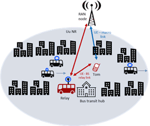
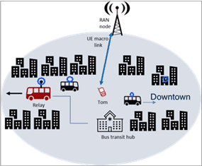
Tom lives in a residential area within walking distance of the city center. He gets good 5G service from the macro network around his house. Tom works in the city center and likes to go to the office on foot. Often, he takes conference calls from his smartphone on his way to work.
It is assumed that
- Primary RAN connectivity should be provided via a macro RAN link (i.e. non relayed link, as opposed to a link via a mobile BS relay). This may increase connection quality and availability, e.g. in case macro RAN connectivity uses lower frequency bands than BS relays, or in areas where vehicles (with mobile BS relays) are moving quickly and/or may provide only temporary connectivity.
- The RAN cell (re)selection settings are such that Tom's UE tries to camp/reselect to a macro RAN node (preferred versus a mobile base station relay), if macro RF quality is suitable. This will increase the possibility to set up a 5G connection via the macro RAN as primary link.
- The simultaneous UE access links to the RAN (via the macro link and mobile BS relay) could be connected to the same or different RAN node(s).
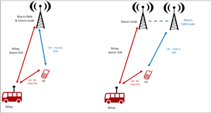
Figure 5.13: Simultaneous UE connection to RAN (via macro link and mobile relay link)
(⇒ copy of original 3GPP image)
(⇒ copy of original 3GPP image)
In the service flow below, the figures show the case of same (or co-located) RAN nodes, for simplicity.
5.13.3 Service Flows p. 36
(1)
It's 7:55 am and Tom gets out of his house to walk to work. His phone camps on a macro cell on frequency f1. Tom has a conference call at 8 am so he starts the conferencing app on his phone and connects his headset.
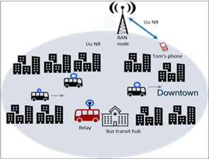
(2)
At 8:25 am, Tom arrives in the city center. Tom's boss asks him to urgently email him documents related to the project Tom is working on, in preparation for a briefing with executives.
(3)
Due to the high-rise buildings in the center, the macro coverage gets spotty, and due to the high number of UEs, the data rate allocated to Tom's phone starts going down. Tom starts emailing the documents to his boss but the upload speed is very slow.
(4)
Tom arrives next to the bus transit hub, where a bus equipped with a mobile base station relay operating on frequency f2 is parked. The macro network determines that Tom's phone can get supplemental throughput from the relay in the bus and adds the relay as secondary node.
(5)
Tom's phone regains good data rate performance, and all his documents are uploaded successfully.
(8)
Tom ends his conference call.
5.13.4 Post-conditions p. 37
Tom is very pleased that he was able to upload all his documents in time, while participating in the conference call without service interruption throughout his commute to work.
Upon call release, based on RAN settings (as described in the pre-conditions), Tom's phone camps on the macro cell, rather than surrounding mobile base station relays.
5.13.5 Existing features partly or fully covering the use case functionality p. 37
Current requirements (e.g. related to wireless self-backhaul, see clause 6.12 of TS 22.261) or existing functionalities (e.g. IAB plus CA/DC), cover some scenarios of simultaneous connectivity between relay and macro nodes, and do not assume or fully address physical relay mobility.
5.13.6 Potential New Requirements needed to support the use case p. 37
[PR.5.13.6-001]
The 5G system shall be able to efficiently control UE idle mode mobility when mobile base station relays are used, e.g. to facilitate UEs connecting to the macro RAN (as opposed to a vehicle relay).
[PR.5.13.6-002]
The 5G system shall be able to support simultaneous UE connectivity to RAN, using a direct UE access link to the macro RAN together with an access link via a mobile base station relay (e.g. mounted on a vehicle).
![]()
![]()
![]()