Content for TR 22.839 Word version: 18.1.0
5.18 Monitoring of vehicle-mounted relays
5.19 Simultaneous connectivity via multiple mobile BS relays
...
...
5.18 Monitoring of vehicle-mounted relays p. 43
5.18.1 Description p. 43
A transportation company CityBus owning a fleet of public buses equipped with mobile base station relays wants to identify the most in-demand/out-of-demand itineraries, peak/off-peak hours, areas with poor 5G connectivity.
The 5G network constantly logs some statistics data related to mobile base station relays on the buses for example, number of UEs connected at the moment, amount of traffic relayed, current location, etc. This kind of data can be helpful for CityBus to improve and optimize its transportation system e.g., add new routes or change existing routes, ask the serving MNO to deploy additional terrestrial base stations along the itineraries for better 5G connectivity/coverage.
5.18.2 Pre-conditions p. 44
To enable this use, following pre-conditions should be met:
- Buses of CityBus are equipped with 5G mobile base stations relays.
- The 5G network is capable to monitor mobile base station relays and periodically generate monitoring data. The features to capture in the monitoring data and the periodicity of generating them are configured by CityBus.
- CityBus is authorized to collect monitoring data for the mobile base station relays. The monitoring data can be collected in real-time as soon as a new monitoring record is generated or for a specified period of time.
- CityBus has a commercial agreement with a serving MNO to monitor mobile base station relays and collect monitoring data via its network.
5.18.3 Service Flows p. 44
- The 5G network monitors all mobile base station relays installed on CityBus's buses as configured by CityBus.
- CityBus retrieves the monitoring data from the 5G network.
- CityBus analyses the retrieved data and identifies that some routes are more in-demand and require buses to run more frequently. Additionally, some areas along some itineraries with poor 5G connectivity are identified.
5.18.4 Post-conditions p. 44
CityBus deploys more buses for identified on-demand routes and the serving MNO deploys additional base stations in identified areas with poor 5G connectivity. Passengers of CityBus are happy that buses are less crowded and enjoy improved 5G experience now.
5.18.5 Existing features partly or fully covering the use case functionality p. 44
The 5G system shall provide a mechanism for supporting real time E2E QoS monitoring within a system.
The 5G system shall be able to provide real time QoS parameters and events information to an authorized application / network entity.
Based on operator policy, the 5G network shall provide suitable APIs to allow a trusted third-party application to request appropriate QoE from the network.
Based on operator policy, the 5G network shall expose a suitable API to an authorized third-party to provide the information regarding the availability status of a geographic location that is associated with that third-party.
Based on operator policy, the 5G network shall expose a suitable API to allow an authorized third-party to monitor the resource utilisation of the network service (radio access point and the transport network (front, backhaul)) that are associated with the third-party.
5.18.6 Potential New Requirements needed to support the use case p. 44
[PR 5.18-1]
The 5G system shall support means to expose monitoring information of a mobile base station relay (e.g. number of UEs connected, QoS, geographical location, time of data monitoring/collection, etc.) to an authorized third-party based on monitoring parameters configured by the authorized third-party (e.g. data to monitor/collect, periodicity/schedule of monitoring, etc.).
5.19 Simultaneous connectivity via multiple mobile BS relays p. 45
5.19.1 Description p. 45
In certain scenarios, where the UE is in the proximity of multiple mobile BS relays, it maybe convenient to use simultaneous connectivity to the macro RAN via more than one BS relay, e.g. to improve data rate, latency and/or increase communication reliability or robustness.
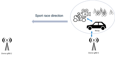
One example, already described in other use case (sec 5.11.2.2), is the outdoor sport race/event, where 5G UEs (e.g. cameras), mounted on motorbikes' following the race, transmit real-time video via relays mounted on alongside vehicles, e.g. provided by the event organizer or TV broadcaster.

In this scenario, depending on the radio conditions, required QoS, and available itinerary information, e.g. on number of vehicles with onboard relays planned to follow the race (maybe different in different parts of the itinerary), the network can decide to exploit simultaneous UE connectivity via two nearby mobile relays, if/when suitable.
5.19.2 Pre-conditions p. 45
5G UEs/cameras, and mobile BS relays mounted on vehicles, are provided by a local TV broadcaster, all pre-provisioned and configured to connect to a certain 5G PLMN network, with a sufficient RAN coverage for the mobile BS relays via dedicated donor RAN nodes covering the sport race itinerary. It is assumed that both relays and donor RAN nodes are part of the same PLMN.
5.19.3 Service Flows p. 45
1)
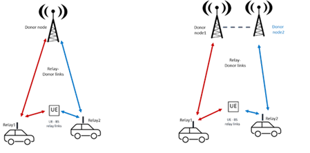
The two simultaneous mobile relay links could be connected to the same or different donor RAN node, as illustrated below.
The race is ongoing, and a certain UE (camera) is connected via one mobile BS relay mounted on a surrounding vehicle (from the TV broadcaster), as shown in figure 1.
2)
After a while, e.g. when the road size get larger, a second vehicle, equipped with a mobile BS relay from the TV broadcaster, approaches the peloton and the UE.
RAN, based on RF measurements, mobility configuration, or other available information (e,g, the identified additional vehicle will be within a close distance from the UE for a certain amount of time/itinerary), decides to add a simultaneous radio link, for that UE, via the second vehicle's mobile relay .

Figure 5.19-2: Simultaneous radio links via multiple mobile BS relays
(⇒ copy of original 3GPP image)
(⇒ copy of original 3GPP image)
3)
Later on, e.g. when the road gets narrower and/or one of the vehicles moves away from the UE, the RAN may remove the corresponding mobile BS relay link.
5.19.4 Post-conditions p. 46
UE connectivity and performance can exploit more robust and better performance using simultaneous mobile BS relay links, when multiple nearby vehicles are available.
5.19.5 Existing features partly or fully covering the use case functionality p. 46
Maybe partly covered by existing IAB, and related DC/CA functionalities, which do not assume full mobility of the relay nodes.
5.19.6 Potential New Requirements needed to support the use case p. 46
[PR 5.19-1]
The 5G system shall be able to support simultaneous UE connectivity to RAN using multiple access links provided via different mobile base station relays (e.g. mounted on different vehicles).
[PR 5.19-2]
The 5G system shall be able to support, for a UE simultaneously connected to RAN via different mobile base station relays (e.g. mounted on vehicles), service continuity during various mobility events, e.g. when the connected mobile BS relays and/or the macro donor node(s) change.