Content for TR 22.839 Word version: 18.1.0
5.6 Keep connectivity via mobile base station relay
5.7 Optimizing mobility for UEs
5.8 Load balancing for mobile base station relays
5.9 Provide location service to a UE attached to the relay mounted in the vehicle
5.10 Incentives and charging
...
...
5.6 Keep connectivity via mobile base station relay p. 16
5.6.1 Description p. 16
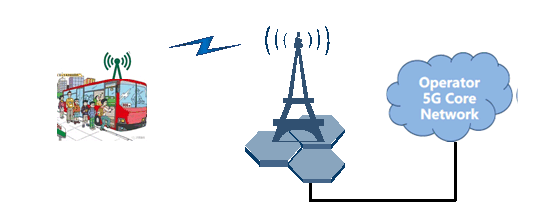
In the urban environment, especially during the rush hour, a high density of passengers is waiting at the bus stop, which puts forwards a high demand for 5G area traffic capacity. A fleet of buses with on board base stations act as relays, which are expected to provide an efficient content delivery to these passengers. The buses typically move at a low speed and usually follow a certain predictable itinerary, along which the extra cellular capacity requirements are fulfilled.

Figure 5.6-1: Connectivity maintenance via mobile base station relay
(⇒ copy of original 3GPP image)
(⇒ copy of original 3GPP image)
5.6.2 Pre-conditions p. 17
To enable this use, following pre-conditions should be met:
- A bus shall be equipped with a mobile base station relay.
- The mobile base station relay is capable of providing 5G connectivity to UEs in the bus along the bus itinerary.
- The mobile base station relay is able to connect the NG-RAN and 5G Core network.
5.6.3 Service Flows p. 17
- At a bus stop, there are two bus lines and passengers are either waiting for bus A or bus B.
- Before the bus is arriving, 5 people are waiting at the bus stop, namely #1, #2, #3, #4, #5. All of their UEs are connected to the terrestrial base stations.
- When bus A arrives, # 1 and #2 get on bus and their UEs access to the mobile base station relay A. Meanwhile, UEs of #3, #4 and #5 are still connected to the terrestrial base station.
- Bus A leaves the bus stop.
- During the driving process of bus A, UE #1 and UE #2 remain connected through mobile base station relay A.
- When bus A arrives at the next bus stop, # 1 gets off the bus A and UE #1 connects to the terrestrial base station. #2 is still on the bus, and UE #2 remains connected through mobile base station relay A.
- Bus A arrives at the destination, # 2 gets off the bus and connects to other base stations.
5.6.4 Post-conditions p. 17
UEs in the bus are provided with enhanced 5G area traffic capacity by the mobile base station.
5.6.5 Existing features partly or fully covering the use case functionality p. 17
Current stage-1 requirements (e.g. on wireless self-backhaul, in TS 22.261), as well as existing stage-2/3 functionalities and architecture options (e.g. IAB) do not assume or address full relay mobility (e.g. BS relays on board of moving vehicles), thus may not cover the identified new potential requirements, which are intended to be specific to mobile BS relays.
5.6.6 Potential New Requirements needed to support the use case p. 17
[PR 5.6-1]
The 5G system shall support the use of mobile base station relay, which provides 5G access to UEs in the vehicle along the vehicle itinerary.
[PR 5.6-2]
The 5G system shall provide means to ensure that UEs inside a vehicle, once provided with 5G access and connectivity via a mobile base station relay (e.g. mounted on the vehicle), remain connected via the mobile base station relay (e.g. mounted on the vehicle).
5.7 Optimizing mobility for UEs p. 18
5.7.1 Description p. 18
When served by mobile base station relays which are, in nature, mobile (moving around), UEs may experience a large number of unnecessary mobility related burdens, such as unnecessary handovers, selection of a mobile base station relay to connect, and cell reselection.
This use case addresses a scenario that UEs and their nearby mobile base station relay are from the same PLMN in general.
5.7.2 Pre-conditions p. 18
MNO1 operates mobile base station relays R1a and R1b.
UE1a and UE1b are subscribed to MNO1.
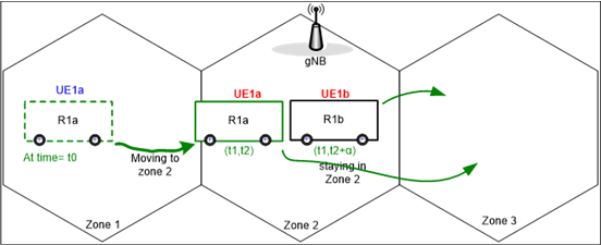
R1a resides in Zone 1 whereas R1b in Zone 2 (refer to Figure below).
UE1a is on R1a whereas UE1b is on R1b.
UE1a does not have active data communication with R1a in Zone 1.
In Zone 2, there is a gNB.

R1a (with UE1a as passenger) moves from Zone 1 into Zone 2 (and stays there from time t1 through time t2) whereas R1b (with UE1b) stays in Zone 2 (from time t1 through time t2+α) before moving to another destinations (e.g., somewhere in zone 3).
5.7.3 Service Flows p. 18
R1a moves from Zone 1 into Zone 2 whereas R1b stays on in Zone 2, and R1a stays in the proximity of R1b.
UE1a wants to initiate data communication and performs smart selection of mobile base station relay/cell to which it can attempt for a connection.
UE1a has estimated that R1a was probably with UE1a for a certain period of time (e.g., by seeing that R1a has been close to UE1a itself for a certain time interval (t0, t1) as shown in the figure).
UE1a tries to initiate a connection with R1a first and gets connected to R1a (Red in the figure, meaning active communication) if available.
Likewise, UE1b attempts to R1b to initiate a connection (Red in the figure, meaning active communication).
5.7.4 Post-conditions p. 19
There is no need to make a handover for UE1a to other mobile base station relays or to other gNB as long as the connectivity provided by R1a is good enough.
UE1a and UE1b continue their travels to the next destination (somewhere out of zone 2, e.g., zone 3) with R1a and R1b, respectively, enjoying their connections with no extra handovers.
5.7.5 Existing features partly or fully covering the use case functionality p. 19
Current stage-1 requirements (e.g. on wireless self-backhaul, in TS 22.261), as well as existing stage-2/3 functionalities and architecture options (e.g. IAB) do not assume or address full relay mobility (e.g. BS relays on board of moving vehicles), thus may not cover the identified new potential requirements, which are intended to be specific to mobile BS relays.
5.7.6 Potential New Requirements needed to support the use case p. 19
[PR 5.7-1]
The 5G system shall be able to provide a means to optimize cell selection and minimize unnecessary cell reselection (between mobile base station relays or between mobile base station relays and fixed gNB,) in the presence of mobile base station relays.
[PR 5.7-2]
The 5G system shall be able to provide a means to minimize unnecessary handover (between mobile base station relays, or between mobile base station relays and a fixed gNB and between) for a UE while served via an mobile base station relay, e.g., based on UE and relay relative mobility or speed.
5.8 Load balancing for mobile base station relays p. 19
5.8.1 Description p. 19
When serving a group of UE's (mostly passengers of a vehicle) via mobile base station relays, the traffic load (simply workload) of a relay can often be different from the others'. In an ordinary moving state of a mobile base station relays, a typical mechanism to make rearrangement of the load (often called load-balancing) is to find whether a macro node (gNB) is available and, if so, to perform necessary handover to that node.
However, in the other states such as temporary stop at a bus stop or at a traffic signal, it is expected that several or more mobile base station relays are around, some of which are more overloaded than the others and therefore are suitable for accepting more UEs, if temporary.
This use case addresses a scenario that some UEs being served by a mobile base station relays can get temporarily rearranged/relocated to anther mobile base station relays (or to macro node, gNB) where they are all from the same PLMN in general.
5.8.2 Pre-conditions p. 19
MNO1 operates mobile base station relays R1a and R1b.
UE(1), UE(2), …, UE(n) are subscribed to MNO1.`
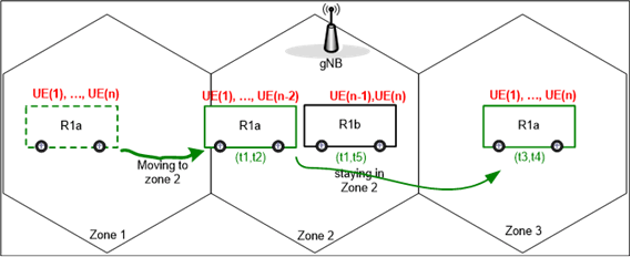
R1a resides in Zone 1 whereas R1b in Zone 2 (refer to Figure below).
UE(1), UE(2), …, UE(n) are on R1a and have active communications in Zone 1 whereas no UEs on R1b have any active communications in Zone 2.
R1a is fairly overloaded/congested due to many UE's competing for network resources.
In Zone 2, there is a gNB.

R1a (with UE(1), …, UE(n) as passengers having active communications) moves from Zone 1 into Zone 2 whereas R1b (with no UEs with active communications) stays in Zone 2.
5.8.3 Service Flows p. 20
R1a moves from Zone 1 into Zone 2 whereas R1b stays on in Zone 2, and R1a stays in the proximity of R1b.
Some UE's, say UE(n-1) and UE(n), out of those being served by R1a are relocated to R1b.
R1a has the burden a little bit alleviated and therefore those UE's, UE(1) through UE(n-2), can enjoy better communication performance during a certain length of time.
R1a has now begun to move to next destination and those UE's (i.e., UE(n-1) and UE(n)) which had temporarily been deported from the steady friend R1a, are getting back to the steady friend.
5.8.4 Post-conditions p. 20
On average UE's using mobile base station relays can get better communication experience.
It was fortunate that the (n-2) UE's can get better communication experience during that time period in Zone 2. They expect that this type of load balance will happen again whenever possible.
5.8.5 Existing features partly or fully covering the use case functionality p. 20
Current stage-1 requirements (e.g. on wireless self-backhaul, in TS 22.261), as well as existing stage-2/3 functionalities and architecture options (e.g. IAB) do not assume or address full relay mobility (e.g. BS relays on board of moving vehicles), thus may not cover the identified new potential requirements, which are intended to be specific to mobile BS relays.
5.8.6 Potential New Requirements needed to support the use case p. 20
[PR 5.8-1]
The 5G system shall be able to provide a means to perform load balancing among mobile base station relays.
5.9 Provide location service to a UE attached to the relay mounted in the vehicle p. 21
5.9.1 Description p. 21
In certain urban environments, tall buildings and other infrastructure sites make GNSS signal too weak for normal UEs, e.g., mobile phones. It is even harder to get GNSS signal when a user is navigating with a mobile phone in a vehicle in urban area.
Some kinds of public vehicles (e.g., bus, light rail train) can take many passengers with a number of UEs. When any of them is using location service or is a target UE in a location service and when UE based location is not possible, e.g. GNSS signals are very weak, the network based location service is used to make sure that the UE can still be located.
In another scenario, the target UE of a location service is in a poor 3GPP coverage area, and it then uses relay mounted in the vehicle to access to the network and to be located.
5.9.2 Pre-conditions p. 21
A bus takes some passengers who get internet service over the 3GPP access through the bus-mounted relay.
The bus-mounted relay gets its location information through GNSS or 3GPP network based location services.
The UEs of some passengers are in low battery.
5.9.3 Service Flows p. 21
Case 1)
The passengers move into an area of poor GNSS coverage when GNSS based location service is used
Case 2)
- A passenger uses an application which need location service. GNSS based location service is used.
- The passengers move into an area of poor GNSS coverage
- The UE or an external AF sends location requests with the requested granularity (e.g. 5 meters) to the 5GS to trigger the network based location service.
- The 5GS responds the location information to the UE or the external AF.
The passengers move into an area of poor 3GPP coverage when 3GPP network based location service is used
- A passenger uses an application which need location service. 3GPP network based location service is used.
- The passengers move into an area of poor 3GPP coverage.
- The passengers uses relay mounted in the vehicle to access to the 3GPP network.
- The UE or an external AF sends location requests to the 5GS with the requested granularity (e.g. 5 meters) to trigger the network based location service.
- The 5GS responds the location information to the UE or the external AF.
5.9.4 Post-conditions p. 21
All passengers who need location service can still get the location information even when they move into an area of poor GNSS coverage or poor 3GPP coverage.
5.9.5 Existing features partly or fully covering the use case functionality p. 21
Current stage-1 requirements (e.g. on wireless self-backhaul, in TS 22.261), as well as existing stage-2/3 functionalities and architecture options (e.g. IAB) do not assume or address full relay mobility (e.g. BS relays on board of moving vehicles), thus may not cover the identified new potential requirements, which are intended to be specific to mobile BS relays.
5.9.6 Potential New Requirements needed to support the use case p. 22
[PR 5.9-1]:
The 5G system shall support providing location service for the UEs accessing to the 5GS network via a mobile base station relay (e.g. mounted on a vehicle).
[PR 5.9-2]:
The 5G system shall support providing location information to a requesting UE or other location entity, for UEs accessing the 5GS network via a mobile base station relay (e.g. mounted on a vehicle), considering e.g. specific location granularity, and efficient UE power consumption.
5.10 Incentives and charging p. 22
5.10.1 Description p. 22
This use case describes the scenario of a transportation company ("Alfa"), owning different fleets of vehicles and transport services in the major cities of the country. Vehicles are for persons or goods transport, e.g taxis, shuttles, buses, vans, and can be equipped (installed or upgraded by the manufacturer) with on board mobile base station relays. The relays can be configured to provide better 5G coverage/connectivity to passengers inside the vehicle (e.g. as premium in-vehicle service), and/or outside users (for localized coverage/capacity boost)
Alfa makes a nationwide commercial agreement with one MNO ("Beta") offering the possibility to use, control and operate the relays on their vehicles. The agreement with Beta includes some direct payment to Alfa, and other arrangements, e.g. free or discounted service for 5G traffic used by Alfa employees or drivers (MNO subscribers) via the vehicle relays.
On the other hand, Beta can offer and apply special subscription tariffs to some of their clients, e.g. enterprises or individual customers for premium in-vehicle 5G experience.
In both cases, it is assumed that the commercial agreements and/or customer tariffs would depend on the amount of data exchanged over the relays, quality of service, and other conditions (maybe specific to certain geographical areas, days/time, users, etc).
5.10.2 Pre-conditions p. 22
The MNO Beta decides to use a certain type and amount of Alfa transport vehicles with relay capabilities, in particular for
- Taxis and shuttles, used by Beta subscribers and/or client enterprises
- Other transport vehicles, used by Beta for outdoor hot spot coverage/capacity boost, according to specific vehicles itineraries, routes (e.g. dense-urban streets), or transit/stop locations (e.g. bus/train stations, stadiums, airports).
5.10.3 Service Flows p. 22
- Relays are activated by Beta.
-
Beta's network and relays collect and report charging data (online and offline) for the 5G traffic exchanged via the vehicle relays managed by Beta, i.e.
- Data exchanged by individual passengers, and experienced QoS, using 5G connectivity via in-vehicle relays
- Overall 5G traffic increase via vehicle relays in specific hot spot areas, days/times.
-
Every billing period, Beta generates related billing records for
- Beta customers and/or client enterprises, paying for in-vehicle premium 5G service as part of their MNO membership/plan.
- Vehicles' drivers and other Alfa employees, eligible for discounted tariffs when using 5G relays (as per deal with Alfa).
- Beta will compensate Alfa for the extra 5G traffic/capacity enabled by the relays, based on the amount of traffic exchanged via the relays, experienced QoS, specific location and time etc., as per their commercial contract and service conditions.
5.10.4 Post-conditions p. 23
Alfa and Beta meet their business goals. Beta customers are very pleased by their in-vehicle 5G experience.
5.10.5 Existing features partly or fully covering the use case functionality p. 23
Current stage-1 requirements (e.g. on wireless self-backhaul, in TS 22.261), as well as existing stage-2/3 functionalities and architecture options (e.g. IAB) do not assume or address full relay mobility (e.g. BS relays on board of moving vehicles), thus may not cover the identified new potential requirements, which are intended to be specific to mobile BS relays.
5.10.6 Potential New Requirements needed to support the use case p. 23
[PR 5.10-1]
The 5G system shall be able to configure and provision specific required QoS for traffic relayed via a mobile base station relay, e.g. may be based on user's subscription, geographical area, day/time of operation. relay type, itinerary/mobility, etc.
[PR 5.10-2]
The 5G system shall be able to identify and differentiate the traffic relayed via a mobile base station relay, e.g. to apply specific charging policies.
[PR 5.10-3]
Online and offline charging shall be supported for UEs connected via a mobile base station relay.
[PR 5.10-4]
The 5G system shall be able to provide and collect charging information for UEs using a mobile base station relay, including e.g.:
- Identification of UEs/users involved;
- Initiation/termination time of relay communication;
- Duration and amount of data transmitted and received;
- Type of service, QoS, other allocated resources (e.g. spectrum);
- Geographic location(s) served by the relay
- Other relay mobility information (e.g. itinerary, speed)