Content for TS 37.340 Word version: 18.1.0
1…
4…
4.2…
4.3…
5…
7…
8…
9
10…
10.2…
10.2.2…
10.3…
10.3.2
10.4…
10.5…
10.5.2
10.6
10.7…
10.8…
10.9…
10.10…
10.11…
10.12…
10.12.2
10.13…
10.14…
10.15
10.16…
10.17…
10.18…
10.19…
10.20
11…
A
B…
4 Multi-Radio Dual Connectivity
4.1 General
4.1.1 Common MR-DC principles
4.1.2 MR-DC with the EPC
4.1.3 MR-DC with the 5GC
4.1.3.1 E-UTRA-NR Dual Connectivity
4.1.3.2 NR-E-UTRA Dual Connectivity
4.1.3.3 NR-NR Dual Connectivity
...
...
4 Multi-Radio Dual Connectivity p. 10
4.1 General p. 10
4.1.1 Common MR-DC principles p. 10
Multi-Radio Dual Connectivity (MR-DC) is a generalization of the Intra-E-UTRA Dual Connectivity (DC) described in TS 36.300, where a multiple Rx/Tx capable UE may be configured to utilise resources provided by two different nodes connected via non-ideal backhaul, one providing NR access and the other one providing either E-UTRA or NR access. One node acts as the MN and the other as the SN. The MN and SN are connected via a network interface and at least the MN is connected to the core network.
The MN and/or the SN can be operated with shared spectrum channel access.
All functions specified for a UE may be used for an IAB-MT unless otherwise stated. Similar as specified for UE, the IAB-MT can access the network using either one network node or using two different nodes with EN-DC and NR-DC architectures. In EN-DC, the backhauling traffic over the E-UTRA radio interface is not supported.
4.1.2 MR-DC with the EPC p. 10
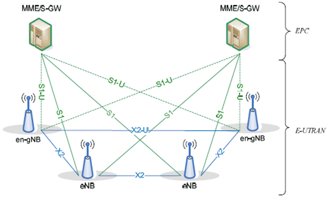
E-UTRAN supports MR-DC via E-UTRA-NR Dual Connectivity (EN-DC), in which a UE is connected to one eNB that acts as a MN and one en-gNB that acts as a SN. The eNB is connected to the EPC via the S1 interface and to the en-gNB via the X2 interface. The en-gNB might also be connected to the EPC via the S1-U interface and other en-gNBs via the X2-U interface.
The EN-DC architecture is illustrated in Figure 4.1.2-1 below.

4.1.3 MR-DC with the 5GC p. 11
4.1.3.1 E-UTRA-NR Dual Connectivity p. 11
NG-RAN supports NG-RAN E-UTRA-NR Dual Connectivity (NGEN-DC), in which a UE is connected to one ng-eNB that acts as a MN and one gNB that acts as a SN.
4.1.3.2 NR-E-UTRA Dual Connectivity p. 11
NG-RAN supports NR-E-UTRA Dual Connectivity (NE-DC), in which a UE is connected to one gNB that acts as a MN and one ng-eNB that acts as a SN.
4.1.3.3 NR-NR Dual Connectivity p. 11
NG-RAN supports NR-NR Dual Connectivity (NR-DC), in which a UE is connected to one gNB that acts as a MN and another gNB that acts as a SN. In addition, NR-DC can also be used when a UE is connected to a single gNB, acting both as a MN and as a SN, and configuring both MCG and SCG.