Content for TS 37.340 Word version: 18.2.0
1…
4…
4.2…
4.3…
5…
7…
8…
9
10…
10.2…
10.2.2…
10.3…
10.3.2
10.4…
10.5…
10.5.2
10.6
10.7…
10.8…
10.9…
10.10…
10.11…
10.12…
10.12.2
10.13…
10.14…
10.15
10.16…
10.17…
10.18…
10.19…
10.20
11…
A
B…
10.14 PDU Session Split at UPF
10.14.1 PDU Session Split at UPF during PDU session resource setup
10.14.2 PDU Session Split at UPF during PDU session resource modify (5GC initiated)
10.14.3 PDU Session Split at UPF (RAN initiated QoS flows offloading from MN to SN)
10.14.4 PDU Session Split at UPF (RAN initiates QoS flows offloading from SN to MN)
...
...
10.14 PDU Session Split at UPF p. 98
10.14.1 PDU Session Split at UPF during PDU session resource setup p. 98
When a new PDU session needs to be established, the 5GC may provide two UL TEID addresses during PDU Session Resource Setup in order to allow for PDU session split. The MN may perform the SN Addition or the MN-initiated SN Modification procedure. If the MN decides to split the PDU session, the MN provides two DL TEID addresses and also the QoS flows associated with each tunnel.
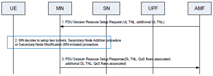
Step 1.
The 5GC provides two UL TEID addresses during PDU Session Resource Setup, to be applied as the first UL tunnel on the NG-U interface and the additional NG-U tunnel in case the MN decides to split the PDU session.
Step 2.
The MN decides to setup two tunnels. The MN uses the SN Addition procedure (as described in clause 10.2.2) or the MN-initiated SN Modification procedure (as described in clause 10.3.2) up to step 6.
Step 3.
The MN provides a DL TEID address to be applied as the first and an additional DL tunnel address on the NG-U interface. The MN also provides which QoS flows are associated with which tunnel.
10.14.2 PDU Session Split at UPF during PDU session resource modify (5GC initiated) p. 99
The 5GC may provide an additional UL TEID address during PDU Session Resource Modify in order to allow the MN to split the PDU session. The MN may perform the SN Addition or the MN-initiated SN Modification procedure. If the MN decides to split the PDU session, the MN provides a DL TEID address to be applied as the additional DL tunnel address and the QoS flows associated with that tunnel.
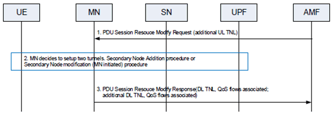
Step 1.
The 5GC provides an additional UL TEID address during PDU Session Resource Modify, to be applied as the additional NG-U tunnel in case the MN decides to split the PDU session.
Step 2.
The MN decides to setup two tunnels. If the new tunnel is to be setup at the SN, the MN uses the SN Addition procedure (as described in clause 10.2.2) or the MN-initiated SN Modification procedure (as described in clause 10.3.2) up to step 6, or up to step 8 if a QoS flow is moved to the SN and data forwarding applies.
Step 3.
The MN provides a DL TEID address to be applied as the additional DL tunnel address on the NG-U interface and the QoS flows associated with that tunnel.
10.14.3 PDU Session Split at UPF (RAN initiated QoS flows offloading from MN to SN) p. 99
When some QoS flows are offloaded from the MN to the SN, the MN may decide to split the PDU session served by the MN into more than one NG-U tunnels. The MN sends the SN Addition/Modification Request message including UPF UL TEID address used at the MN. Later on, if the MN receives a new UL TEID in the PDU Session Resource Modify Confirm message, the MN may provide the new UL TEID to the SN.
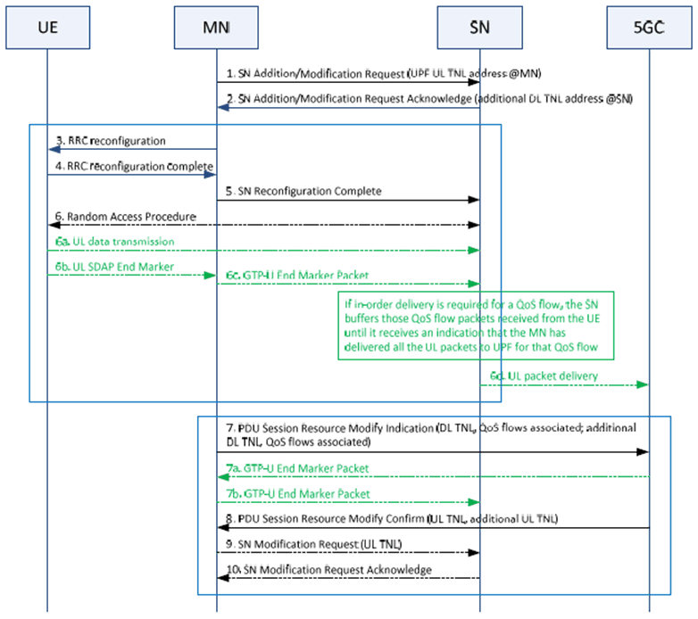
Figure 10.14.3-1: PDU Session Split at UPF during RAN initiated PDU session resource modify (QoS flows offloading from MN to SN)
(⇒ copy of original 3GPP image)
(⇒ copy of original 3GPP image)
Step 1-2.
If the MN decides to split a PDU session, it uses the SN Addition procedure or the MN-initiated SN Modification procedure, including current UPF UL NG-U tunnel used at the MN. If in-order delivery is required for some QoS flows, an UL forwarding tunnel may be setup for the PDU session at this stage.
Step 3-6d.
If in-order delivery is required, the SN buffers the first packets received from the UE for a certain QoS flow until it receives an GTP-U end marker packet over the UL forwarding tunnel indicating that the MN has delivered all UL packets from the source side to UPF for that QoS flow. Then the SN starts delivering UL packets to UPF for that QoS flow using the UPF UL TEID address used at the MN received at step 1.
Step 7-8.
The MN uses the PDU Session Resource Modify Indication message to inform 5GC that the PDU session is split into two tunnels and indicate which QoS flows are associated with which DL tunnel. The 5GC triggers the sending of DL End Marker packets without QFI tag at step 7a and confirms with the PDU Session Resource Modify Confirm message and allocates corresponding uplink tunnels.
After receiving the End Marker packet(s) from UPF at step 7a, the MN determines that the End Marker packets only work on the offloaded QoS flows, and may stop delivering and discard DL packets of the offloaded QoS flows, and the MN shall continue transmiting DL packets for the not offloaded QoS flows, if any.
Step 7a./7b.
After receiving the DL end marker from 5GC at step 7a, the MN may generate at step 7b DL End Marker packets without QFI tag towards the SN.
Step 9-10.
If the MN receives a new UL TEID in the PDU Session Resource Modify Confirm message for itself, the MN will use it to deliver UL packets to UPF. If the MN receives a new UL TEID for the SN, then the MN-initiated SN Modification procedure (i.e., step 9 and step 10) is used to provide the new UL TEID to the SN and then the SN switches to use the new UL TEID to deliver UL packets.
10.14.4 PDU Session Split at UPF (RAN initiates QoS flows offloading from SN to MN) |R17| p. 101
When some QoS flows are offloaded from the SN to the MN, the MN may decide to split the PDU session served by the SN into more than one NG-U tunnels. If the MN requests to offload, the MN sends the SN Modification Request message to the SN. In case the SN requests to offload, the SN sends the SN Modification Required message to the MN.
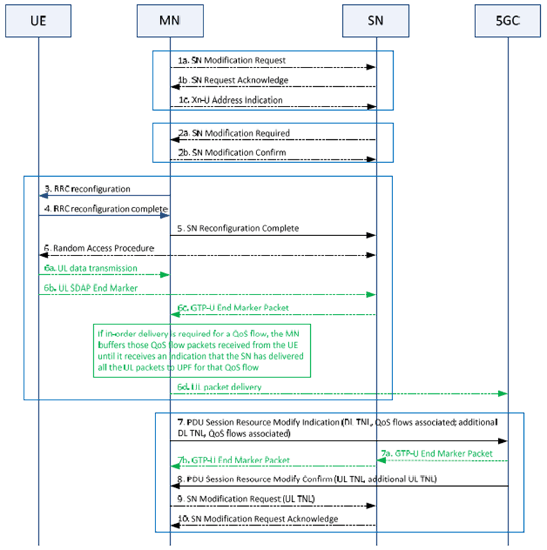
Figure 10.14.4-1: PDU Session Split at UPF during RAN initiated PDU session resource modify (QoS flows offloading from SN to MN)
(⇒ copy of original 3GPP image)
(⇒ copy of original 3GPP image)
Step 1a-1c.
When the MN requests to offload some QoS flows from the SN to the MN for a PDU session, it sends the SN Modification Request message. If in-order delivery is required for some of the QoS flows, an UL forwarding tunnel may be setup for the PDU session at this stage and the MN provides the UL forwarding tunnel address information in the Xn-U Address Indication message.
Step 2a-2b.
When the SN requests to offload some QoS flows to the MN for a PDU session, the SN sends the SN Modification Required message. If in-order delivery is required for some of the QoS flows, an UL forwarding tunnel may be setup for the PDU session at this stage and the MN provides the UL forwarding tunnel address information in the SN Modification Confirm message.
Step 3-6d.
If in-order delivery is required, the MN buffers the first packets received from the UE for a certain QoS flow until it receives an GTP-U end marker packet over the UL forwarding tunnel indicating that the SN has delivered all UL packets from the source side to UPF for that QoS flow.
Step 7-8.
The MN uses the PDU Session Resource Modify Indication message to inform 5GC that the PDU session is split into two tunnels and indicate which QoS flows are associated with which DL tunnel. The 5GC triggers the sending of DL End Marker packets without QFI tag at step 7a and confirms with the PDU Session Resource Modify Confirm message and allocates corresponding uplink tunnels.
After receiving the End Marker packet(s) from UPF at step 7a, the SN determines that the End Marker packets only work on the offloaded QoS flows, and may stop delivering and discard DL packets of the offloaded QoS flows, and the SN shall continue transmiting DL packets for the not offloaded QoS flows, if any.
Step 7a./7b.
After receiving the DL end marker from 5GC at step 7a, the SN may generate at step 7b DL End Marker packets without QFI tag towards the MN.
Step 9-10.
If the MN receives a new UL TEID in the PDU Session Resource Modify Confirm message for itself, the MN will use it to deliver UL packets to UPF. If the MN receives a new UL TEID for the SN, then the MN-initiated SN Modification procedure (i.e., the step 9 and step 10) is used to provide the new UL TEID to the SN and then the SN switches to use the new UL TEID to deliver UL packets.
![]()
![]()
![]()