Content for TS 23.402 Word version: 18.3.0
0…
4…
4.2…
4.2.2
4.2.3
4.3…
4.4…
4.5…
4.5.7…
4.6…
4.7…
4.7.2…
4.8…
4.8.2a…
4.9…
5…
5.2…
5.4…
5.5
5.6…
5.7…
5.8…
6…
6.2…
6.3
6.4…
6.4.3…
6.5…
6.6…
6.7…
6.8…
6.10…
6.13…
6.15…
7…
7.2…
7.3
7.4…
7.5…
7.6…
7.8…
7.10…
8…
8.2.1.2
8.2.1.3…
8.2.2
8.2.3…
8.2.6…
8.3…
8.4…
8.5…
9…
9.3…
9.4…
10…
13…
16…
16.1.2…
16.1.6…
16.2…
16.2.1a…
16.3…
16.4…
16.7…
16.8…
16.10…
17…
A…
C…
E…
16.10 Handover procedure from 3GPP access to WLAN on S2a
16.10.1 Handover procedure from 3GPP access to WLAN on S2a in single-connection mode
16.10.2 Handover procedure from 3GPP access to WLAN on S2a in multi-connection mode
16.11 Handover procedure from WLAN on S2a to 3GPP access
...
...
16.10 Handover procedure from 3GPP access to WLAN on S2a |R12| p. 289
16.10.1 Handover procedure from 3GPP access to WLAN on S2a in single-connection mode p. 289
16.10.1.1 Handover in single-connection mode from 3GPP access to WLAN on GTP S2a p. 289
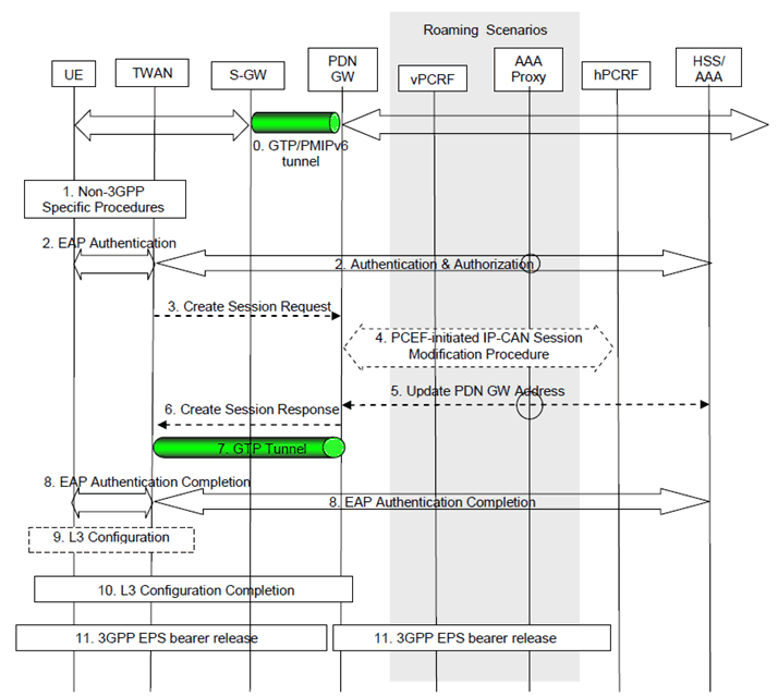
This procedure is used in the single-connection mode to hand over a single PDN Connection from 3GPP access to WLAN. The decision to use the single-connection mode is made during authentication as described in clause 16.2.

Figure 16.10.1.1-1: Handover in single-connection mode from 3GPP access to Trusted WLAN on GTP S2a for roaming and non-roaming scenarios
(⇒ copy of original 3GPP image)
(⇒ copy of original 3GPP image)
The home routed roaming, LBO and non-roaming scenarios are depicted in the Figure 16.2.1-1:
- In the LBO case, the 3GPP AAA Proxy acts as an intermediary, forwarding messages from the 3GPP AAA Server in the HPLMN to the PDN-GW in the VPLMN and vice versa. Messages between the PDN-GW in the VPLMN and the hPCRF in the HPLMN are forwarded by the vPCRF in the VPLMN.
- In the home routed roaming and non-roaming cases, the vPCRF is not involved, except for the authentication and authorization in step 2.
- In the non-roaming cases, the 3GPP AAA Proxy is not involved. In home routed roaming case, the 3GPP AAA Proxy is not involved in step 5.
- Step 0. The UE is connected in the 3GPP Access and has a PMIPv6 or GTP tunnel on the S5/S8 interface.
-
Step 2. This step is the same as step 2 in 16.2.1 for non-emergency sessions and as step 2 in clause 16.2.1a for emergency sessions with the following addition: If the UE indicates single-connection, then the UE indicates also handover via EAP-AKA' to 3GPP AAA.
For emergency sessions, following modifications apply:
- During authentication and authorization, the HSS shall provide the AAA server with the "PDN-GW currently in use for emergency services", if available, as part of the subscription information, relayed by the AAA server to the TWAN;
- If the UE indicated an handover attach in step 2 is non-roaming and has been successfully authenticated, and based on operator policy, the TWAN may select the "PDN-GW currently in use for emergency services" , if available, as anchor PDN-GW. Otherwise, e.g. if the UE indicated an handover attach in step 2 and has been authorized but not authenticated, or the UE is roaming ,or based on operator configuration (e.g. the network supports handovers to/from HRPD), the TWAN shall select the PDN-GW that is statically configured in the TWAN Emergency Configuration Data.
- Step 3. This step is the same as step 3 in clause 16.2.1 with the following addition: The handover indication is set in the Create Session Request to allow the PDN-GW to re-allocate the same IP address or prefix that was assigned to the UE while it was connected to the 3GPP access and to initiate a PCEF-Initiated IP-CAN Session Modification Procedure with the PCRF.
- Step 4. The PDN-GW executes a PCEF-Initiated IP-CAN Session Modification Procedure with the PCRF as specified in TS 23.203. The Event Report indicates the change in Access Type. If the PDN-GW decides to allocate a new IP address/prefix instead of preserving the old IP address/prefix, as described in clause 4.1.3.2.3, the PDN-GW executes an IP-CAN session Establishment Procedure with the PCRF instead of a PCEF-Initiated IP-CAN Session Modification Procedure.
- Step 6. The PDN-GW responds with a Create Session Response (PDN-GW Address for the user plane, PDN-GW TEID of the user plane, PDN-GW TEID of the control plane, PDN Type, PDN Address, EPS Bearer Identity, EPS Bearer QoS, APN-AMBR, Charging ID, Cause). The Create Session Response contains the IP address and/or the prefix that was assigned to the UE while it was connected to the 3GPP IP access. The Charging Id provided by the PGW is the Charging Id previously assigned to the default bearer of the PDN connection in the 3GPP access. For emergency sessions, the TWAN also includes the PDN-GW address obtained in step 4. Depending upon the active PCC rules, the PDN-GW may create dedicated bearers on S2a interface. And in that case, it applies the Charging ID previously in use for the corresponding dedicated bearer(s) while the UE was connected to the 3GPP IP access (i.e. bearer with the same QCI and ARP as in 3GPP access).
- Step 10: This step is the same as step 15 in clause 16.2.1.
- Step 11. The PDN-GW shall initiate the PDN-GW Initiated PDN Disconnection procedure in 3GPP access as defined in clause 5.6.2.2 or the PDN-GW Initiated Bearer Deactivation procedure as defined in clause 5.4.4.1 of TS 23.401.
16.10.1.2 Handover in single-connection mode from 3GPP access to WLAN on PMIP S2a p. 292

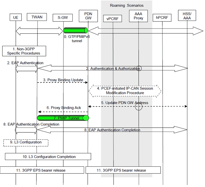
Figure 16.10.1.2-1: Handover in single-connection mode from 3GPP access to Trusted WLAN on PMIP S2a for roaming and non-roaming scenarios
(⇒ copy of original 3GPP image)
(⇒ copy of original 3GPP image)
The procedure is based on clause 16.2.2 with the following differences:
- Step 0: The UE is connected in the 3GPP Access and has a PMIPv6 or GTP tunnel on the S5/S8 interface.
- Step 2: This step is the same as step 2 in clause 16.2.2 with the following addition: If the UE indicates single-connection, then the UE indicates also handover via EAP-AKA' to 3GPP AAA. If the UE requests a PDN type, and this PDN type is not possible, then the request is rejected with a relevant authorization failure.
- Step 3: This step is the same as step 3 in clause 16.2.2 with the following addition: The handover indicator is set in the Proxy Binding Update to allow the PDN-GW to re-allocate the same IP address or prefix that was assigned to the UE while it was connected to the 3GPP access and to initiate a PCEF-Initiated IP-CAN Session Modification Procedure with the PCRF.
- Step 4: The PDN-GW executes a PCEF-Initiated IP-CAN Session Modification Procedure with the PCRF as specified in TS 23.203. The Event Report indicates the change in Access Type.
- Step 6: Tthe PDN-GW sends a Proxy Binding Acknowledgement message. The details of the Proxy Binding Acknowledgement message are described in step 6 in clause 16.2.2. The Proxy Binding Acknowledgement message contains the IP address and/or the prefix that was assigned to the UE while it was connected to the 3GPP IP access.
- Step 10: This step is the same as step 15 in clause 16.2.2.
- Step 11: The PDN-GW shall initiate the PDN-GW Initiated PDN Disconnection procedure in 3GPP access as defined in clause 5.6.2.2 or the PDN-GW Initiated Bearer Deactivation procedure as defined in clause 5.4.4.1 of TS 23.401.
16.10.2 Handover procedure from 3GPP access to WLAN on S2a in multi-connection mode p. 293
16.10.2.1 Handover in multi-connection mode from 3GPP access to WLAN on GTP S2a p. 293
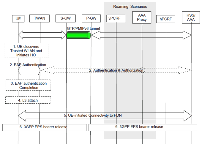
The following procedure is used to handover one or more PDN connections from 3GPP access to the Trusted WLAN.The steps involved in this procedure are depicted below for both the non-roaming and roaming cases. It is assumed that while the UE is served by the 3GPP access, PMIPv6 or GTP tunnel(s) are established between the Serving-GW and the PDN-GW in the EPC.

Figure 16.10.2.1-1: Handover from 3GPP access to Trusted WLAN on GTP S2a for roaming and non-roaming scenarios
(⇒ copy of original 3GPP image)
(⇒ copy of original 3GPP image)
In the Local Breakout case, the 3GPP AAA Proxy forwads messages from the 3GPP AAA Server in the HPLMN to the PDN-GW in the VPLMN and vice versa. Messages between the PDN-GW in the VPLMN and the hPCRF in the HPLMN are forwarded by the vPCRF in the VPLMN. In the home routed roaming and non-roaming cases, the vPCRF and the 3GPP AAA Proxy are not involved, except for the authentication and authorization in step 2.
For connectivity to multiple PDNs the following applies:
- If the UE is connected to both 3GPP access and TWAN before the handover of PDN connection(s) to Trusted WLAN is triggered, steps 1 to 4 shall be skipped and the UE shall only perform step 5 for each PDN connection that is being transferred from 3GPP access.
- If the UE is connected only to 3GPP access before the handover of PDN connection(s) to Trusted WLAN is triggered, steps 1 to 4 shall be performed. The UE shall then repeat step 5 for each of the PDN connections that is being transferred from 3GPP access.
- Step 6 shall be repeated for each PDN connection that is being transferred from 3GPP access.
Step 0.
Depending upon the active PCC rules, the PDN-GW may create dedicated bearers on S2a interface. And in that case, it applies the Charging ID previously in use for the corresponding dedicated bearer(s) while the UE was connected to the 3GPP IP access (i.e. bearer with the same QCI and ARP as in 3GPP access).
The UE is connected in the 3GPP access and has PMIPv6 or GTP tunnel(s) on the S5/S8 interface.
Step 1.
The UE discovers the trusted WLAN access and determines to transfer one or more of its active PDN connections from the currently used 3GPP access to the discovered trusted WLAN.
Step 2.
The UE performs access authentication and authorization in the trusted WLAN. This step is the same as step 2 of the initial attach procedure in clause 16.2.1 for non-emergency sessions and in clause 16.2.1a for emergency sessions, where in this case Multi-Connection Mode is requested by the UE.
For emergency sessions, following modifications apply:
Step 3.
- During authentication and authorization, the HSS shall provide the AAA server with the "PDN-GW currently in use for emergency services", if available, as part of the subscription information, relayed by the AAA server to the TWAN;
- If the UE indicated an handover attach in step 2 is non-roaming and has been successfully authenticated, based on operator policy, the TWAN may select the "PDN-GW currently in use for emergency services" as anchor PDN-GW. Otherwise, e.g. if the UE indicated an handover attach in step 2 and has been authorized but not authenticated), or the UE is roaming, or based on operator configuration (e.g. the network supports handovers to/from HRPD), the TWAN shall select the PDN-GW that is statically configured in the TWAN Emergency Configuration Data.
TWAN sends EAP success to the UE and completing EAP authentication. This step is the same as step 8 of the initial attach procedure in clause 16.2.1.
Step 4.
If NSWO is authorized for the UE in step 2, anytime after step 3 the UE may send a L3 attach request to the TWAN for NSWO and receive the address or prefix of the NSWO from TWAN.
Step 5.
The UE performs UE-initiated connectivity request procedure for Multi-Connection Mode according to clause 16.8.1 with the following exception:
Step 6.
- The UE sends a PDN Connectivity Request message to the TWAN with Request Type indicating "Handover".
- The UE indicates the APN corresponding to the PDN connection which is being handed over to TWAN in the PDN Connectivity Request message. If the APN is not provided, and the subscription context from HSS/AAA contains a PDN-GW identity and APN pair corresponding to the default APN, the TWAN uses the default APN for non-emergency sessions and the emergency APN for emergency sessions.
- Upon receiving the PDN Connectivity Request message, the TWAN selects the PDN-GW as indicated in the subscription data received from the 3GPP AAA Server and sends Create Session Request to the selected PDN-GW. Since the Request Type is "Handover", a Handover Indication is included in the Create Session Request. In the case of emergency sessions when the UE has been authorized but not authenticated, the TWAN selects the PDN-GW that is statically configured in the TWAN Emergency Configuration Data.
- Since it is a handover, the IP-CAN Session Establishment is not performed. The PDN-GW may execute a PCEF-Initiated IP-CAN Session Modification Procedure with the PCRF as specified in TS 23.203 to report e.g. change in IP-CAN type.
The PDN-GW shall initiate the PDN-GW Initiated PDN Disconnection procedure in 3GPP access as defined in clause 5.6.2.2 or the PDN-GW Initiated Bearer Deactivation procedure as defined in clause 5.4.4.1 of TS 23.401.
16.10.2.2 Handover in multi-connection mode from 3GPP access to WLAN on PMIP S2a p. 295
This procedure is as in clause 16.10.2.1 with the following differences:
Step 5 c.
Upon receiving the PDN Connection Request message, the TWAN selects the PDN-GW as indicated in the subscription data received from the 3GPP AAA Server and sends the Proxy Binding Update to the selected PDN-GW by setting the Handover Indicatior to indicate handoff between two different interfaces of the UE. The details of the messages and parameters to be used are described in Steps 6 and 8 in clause 8.2.2. Additionally, the Proxy Binding Update includes the current TWAN Identifier as described in clause 16.1.7 and the UE Time Zone.
16.11 Handover procedure from WLAN on S2a to 3GPP access |R12| p. 295
This procedure is as in clause 8.2.1.1 (GTP-based S5/S8 for E-UTRAN), clause 8.2.1.2 (PMIP-based S5/S8 for E-UTRAN), clause 8.2.1.3 (GTP-based S5/S8 for UTRAN/GERAN) and clause 8.2.1.4 (PMIP-based S5/S8 for GERAN/UTRAN) with the following differences:
- Step 1. There is a GTP or PMIP tunnel between TWAN and PGW.
- Step 18 in clause 8.2.1.1, step 19 in clause 8.2.1.2 and step 17 in clause 8.2.1.3. The PDN-GW shall initiate resource allocation deactivation procedure in the TWAN as defined in clause 16.4.
-
For emergency sessions:
- On step 3, the UE sends an Attach Request to the MME with Request Type indicating "handover for emergency services". The message from the UE is routed by E-UTRAN to the MME as specified in TS 23.401 (E-UTRAN). The UE shall not include any APN.
- On step 4, the MME shall contact the HSS and attempt to authenticate the UE as described in TS 23.401.
- On step 5, if the UE has been successful authenticated, the MME may perform location update procedure and subscriber data retrieval from the HSS as specified in TS 23.401 by which the "PDN-GW currently in use for emergency services" is sent to the MME as part of the subscription information. Since the Request Type is "handover for emergency services", the "PDN-GW currently in use for emergency services" conveyed from the HSS to the MME will be stored in PDN subscription context. The MME receives information on all the PDNs the UE is connected to over the non-3GPP access in the Subscriber Data obtained from the HSS. If the UE has been authorized but not authenticated, Step 5 is skipped.
- On step 6, the MME selects the emergency APN, and a serving GW as described in TS 23.401. If the UE has been successfully authenticated and is not roaming, and based on operator configuration, the MME uses the "PDN-GW currently in use for emergency services" received from the HSS as anchor PDN-GW. Otherwise, e.g. if the UE has not been successfully authenticated, or the UE is roaming, or based on operator configuration (e.g. the network supports handovers to/from HRPD), the MME shall use the PDN-GW that is statically configured in the MME Emergency Configuration Data. The MME sends a Create Session Request (including IMSI, MME Context ID, PDN-GW address, Handover Indication, emergency APN) message to the selected Serving-GW. Since the Request Type is "handover for emergency services", a Handover Indication information is included.
-
For non-emergency and emergency sessions:
- On step 9 of clause 8.2.1.1 and step 11 of clause 8.2.1.3: the Charging Id provided by the PGW to the default and dedicated bearers in 3GPP access is the Charging Id previously assigned to the corresponding default and dedicated bearers (i.e. bearer with the same QCI and ARP) of the PDN connection in the non-3GPP access on the S2a interface, although the Charging Id still applies to the non-3GPP access.
- On step 13 of clause 8.2.1.1 and step 14 of clause 8.2.1.3: the Charging Id previously in use for the default and dedicated bearers in the non-3GPP access on the S2a interface now applies to the corresponding default and dedicated bearers in 3GPP access (i.e. bearer with the same QCI and ARP as in non-3GPP access).