Content for TS 23.402 Word version: 18.3.0
0…
4…
4.2…
4.2.2
4.2.3
4.3…
4.4…
4.5…
4.5.7…
4.6…
4.7…
4.7.2…
4.8…
4.8.2a…
4.9…
5…
5.2…
5.4…
5.5
5.6…
5.7…
5.8…
6…
6.2…
6.3
6.4…
6.4.3…
6.5…
6.6…
6.7…
6.8…
6.10…
6.13…
6.15…
7…
7.2…
7.3
7.4…
7.5…
7.6…
7.8…
7.10…
8…
8.2.1.2
8.2.1.3…
8.2.2
8.2.3…
8.2.6…
8.3…
8.4…
8.5…
9…
9.3…
9.4…
10…
13…
16…
16.1.2…
16.1.6…
16.2…
16.2.1a…
16.3…
16.4…
16.7…
16.8…
16.10…
17…
A…
C…
E…
5.6 Multiple PDN Support with PMIP-based S5/S8
5.6.1 UE requested PDN connectivity
5.6.2 PDN Disconnection
...
...
5.6 Multiple PDN Support with PMIP-based S5/S8 p. 98
5.6.1 UE requested PDN connectivity p. 98
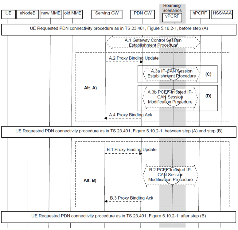
The UE requested PDN connectivity procedure for E-UTRAN is depicted in Figure 5.6.1-1. The procedure allows the UE to request for connectivity to an additional PDN over E-UTRAN, including allocation of a default bearer, when the UE already has active PDN connections over E-UTRAN. This procedure is also used to request for connectivity to an additional PDN over E-UTRAN when the UE is simultaneously connected to E-UTRAN and a non-3GPP access, and the UE already has active PDN connections over both the accesses. In this procedure, the UE is assumed to be in active mode. Proxy Mobile IP is used on S5 or S8 interface. It is assumed that the MAG is collocated with the Serving-GW for the PMIPv6 procedure between the Serving-GW and the PDN-GW.
When only GTP-based S5 or S8 connections are established for roamers from a PMIP network into a GTP network the procedure as described in clause 5.10.2 of TS 23.401 applies.
When PMIP-based S5/S8 is used the EPS bearer identities of the default bearers are used to differentiate the PDN connections for a given APN, i.e. the MN-ID, the APN and the EPS bearer identity of the default EPS bearer identify the PDN connection. The Serving Gateway shall include the EPS bearer identity of the default EPS bearer if multiple PDN connections per APN are supported in the Proxy Binding Update messages. If the EPS bearer identity is included in a Proxy Binding Update, the PDN-GW shall explicitly indicate the support of multiple PDN connections to a given APN. The MME is configured if the Serving-GWs in its PLMN support multiple PDN connections to the same APN over PMIP based S5/S8. If the Serving-GW does not support multiple PDN connections to the same APN and the UE requests a PDN connection for an APN for which the UE already has an active PDN connection, the MME shall reject the PDN connectivity request. If the PDN-GW does not support multiple PDN connections for a given APN, and the Serving-GW supports multiple PDN connections to the same APN and the UE requests a PDN connection for an APN for which the UE already has an active PDN connection, the Serving-GW shall reject the PDN connectivity request.
The procedure is also used for the re-establishment of existing PDN connectivity after the UE performed the handover from non-3GPP accesses for the first PDN connection by the Attach procedure. The UE triggers the re-establishment of existing PDN connectivity after the handover by providing a Request Type indicating "Handover" as specified in TS 23.401.

Figure 5.6.1-1: UE requested PDN connectivity with PMIP-based S5 or S8
(⇒ copy of original 3GPP image)
(⇒ copy of original 3GPP image)
This procedure applies to the Non-Roaming (Figure 4.2.1-1), Roaming (Figure 4.2.1-2) and Local Breakout (Figure 4.2.3-4) cases. For the Roaming and Local Breakout cases, the vPCRF forwards messages between the Serving-GW and the hPCRF. In the Local Breakout case, the vPCRF forwards messages between the PDN-GW and the hPCRF.
The optional interaction steps between the gateways and the PCRF in the procedures in Figure 5.6.1-1 only occur if dynamic policy provisioning is deployed. Otherwise policy may be statically configured with the gateway.
For UE request additional PDN connectivity to PDNs when connected to 3GPP access network with PMIP-based S5 or S8, the IP address is not available after step A1, steps in (Alt A) are performed after step A.1, excluding steps in (Alt B). The step in (C) is performed only when the UE establishes additional PDN connectivity with a PDN it is not already connected to, excluding step (D).
For re-establishment of existing PDN connectivity after the UE performed the handover from non-3GPP accesses, the steps shown in (Alt A) and (Alt B) are mutually exclusive in this procedure, i.e. either steps A.2-A.4 are executed or steps B.1-B.3. In order to execute the alternative (Alt B), the IP address of the UE needs to be available after step A.1. The IP Address(es) of the UE is received in step A.1, if dynamic policy provisioning is deployed. If multiple PDN connections to same APN are supported by the Serving-GW, (Alt A) shall be used in this procedure.
In case the IP address(es) of the UE is available after step A.1, (Alt B) provides lower jitter for dual radio handovers. In case the IP address(es) of the UE is not available after step A.1, (Alt A) shall be used.
For re-establishment of existing PDN connectivity after the UE performed the handover from non-3GPP accesses, the following also applies:
- In step A.2/B.1 the Serving-GW sets the Handover Indicator to indicate handoff between two different interfaces of the UE.
- The step in (D) and step B.2 are performed only when the UE re-establishes PDN connectivity after a handover. The steps in (D) correspond to the PCEF-Initiated IP-CAN Session Modification procedure specified in TS 23.203.
- In step A.4/B.3, the UE Address Info shall contain the IP address the UE obtained during PDN connectivity establishment for this PDN over the non-3GPP access. The PDN-GW also includes the Charging ID for the PDN connection in the Proxy binding acknowledgement. For the case of additional PDN connectivity with a PDN, the PDN-GW generates a Charging Id for the PDN connection. For the case of re-establishment of existing PDN connectivity after the UE performed a handover from non-3GPP access, the PDN-GW reuses the Charging Id previously assigned to the PDN connection if the source access is a PMIP-based access or to the Default Bearer if the source access is GTP-based.
5.6.2 PDN Disconnection p. 100
5.6.2.1 UE, MME or S-GW initiated PDN Disconnection p. 100
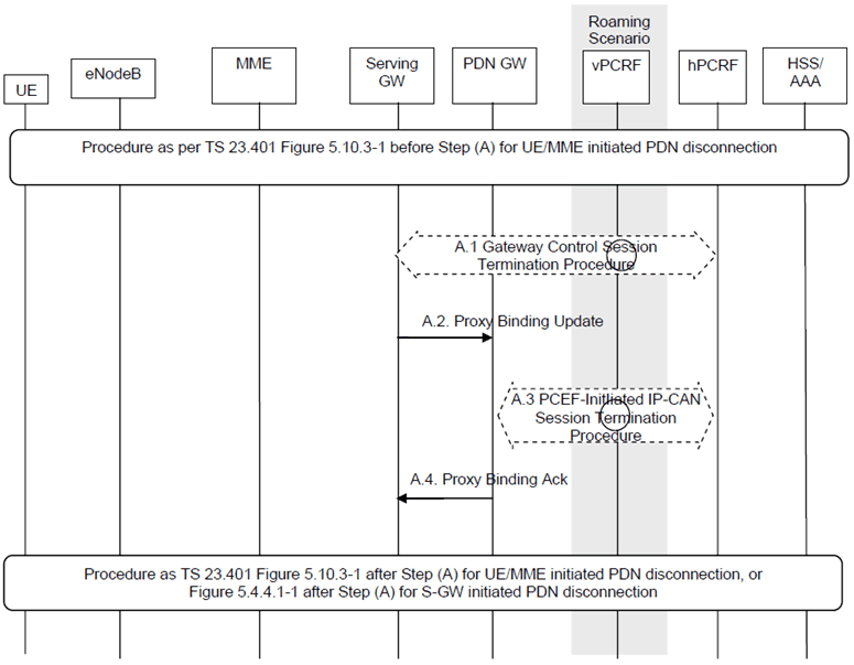
When GTP-based S5 or S8 is used the procedure described in clause 5.10.3 of TS 23.401 applies for the UE or MME initiated PDN disconnection. The PMIP variant of this procedure is specified below. In addition, if the default bearer belonging to a PDN connection is to be deactivated by the S-GW, e.g. due to un-successful modification of QoS of default bearer that was triggered by PCRF interaction, the S-GW deactivates all bearers belonging to the PDN connection using the following procedure.

Figure 5.6.2-1: UE, MME or S-GW initiated PDN disconnection Procedure for PMIP-based S5/S8
(⇒ copy of original 3GPP image)
(⇒ copy of original 3GPP image)
Steps A.1 to A.4 are described in clause 5.3. For the case of S-GW initiated PDN disconnection, which corresponds to PDN-GW initiated bearer deactivation procedure of clause 5.4.4.1 of TS 23.401, the procedure starts from step A.1 and there are no steps corresponding to box (B) of Figure 5.4.4.1-1 of TS 23.401.
5.6.2.2 PDN-GW-initiated PDN Disconnection p. 101
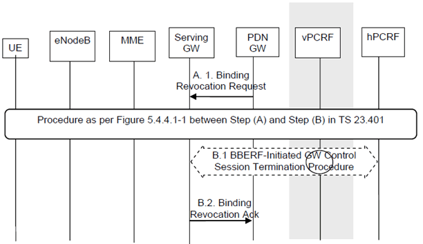
The default bearer and all the dedicated resource allocations associated with the PDN address are released in this procedure.

Figure 5.6.2.2-1: PDN-GW initiated PDN Disconnection Procedure for PMIP-based S5/S8
(⇒ copy of original 3GPP image)
(⇒ copy of original 3GPP image)
This procedure applies to the Non-Roaming (Figure 4.2.1-1), Roaming (Figure 4.2.1-2) and Local Breakout (Figure 4.2.3-4) cases. For the Roaming and Local Breakout cases, the vPCRF forwards messages between the Serving-GW and the hPCRF. In the Local Breakout case, the vPCRF forwards messages between the PDN-GW and the hPCRF.
The optional interaction steps between the gateways and the PCRF in the procedures in Figure 5.6.2.2-1 only occur if dynamic policy provisioning is deployed. Otherwise policy may be statically configured with the gateway.
A.1)
The PDN-GW sends a Binding Revocation Indication (PDN address) message to the Serving-GW.
Steps between A and B are described in clause 5.4.4.1 of TS 23.401, using the indication that all bearers belonging to the given PDN address shall be released.
B.1)
The Serving-GW initiates the Gateway Control Session Termination Procedure with the PCRF as specified in TS 23.203. The S-GW provides the information to enable the PCRF to uniquely identify the IP-CAN session and indicates User Location Information and/or UE Time Zone Information to the PCRF as an Event Report if the corresponding event trigger is set. This results in the removal of the Gateway Control session in S-GW.
B.2)
The Serving-GW returns a Binding Revocation Acknowledgement message to the PDN-GW.