Content for TS 23.379 Word version: 19.2.0
1…
7…
7.4…
10…
10.5…
10.6…
10.6.2.2.13…
10.6.2.2.24…
10.6.2.3…
10.6.2.3.1.2…
10.6.2.3.2…
10.6.2.4…
10.6.2.4.3…
10.6.2.5…
10.6.2.5.2.3…
10.6.2.6…
10.6.2.6.2…
10.6.2.7…
10.6.2.10…
10.6.3…
10.7…
10.7.2.2…
10.7.2.3…
10.7.3…
10.7.4…
10.7.5…
10.7.5.2.3a…
10.7.6…
10.7.6.2.3…
10.9…
10.9.1.3…
10.9.1.3.2…
10.9.1.3.3…
10.9.1.4…
10.9.1.5…
10.9.2…
10.9.2.6…
10.10…
10.12…
10.14…
10.15…
10.19…
10.19.2.11…
10.19.3…
10.19.3.1.4…
10.19.3.2…
10.19.3.2.4…
10.19.3.2.6…
A…
A.4…
B…
10.12 MCPTT media plane transmissions with partner MCPTT systems (on-network)
10.13 Location information (on-network)
...
...
10.12 MCPTT media plane transmissions with partner MCPTT systems (on-network) p. 205
The MCPTT user is able to receive MCPTT media services (e.g. group communication, private calls) from partner MCPTT systems in normal and roaming conditions. In this service delivery model, the media plane transmissions between the MCPTT UE of the user and the partner MCPTT system can be achieved directly or via the primary MCPTT system, selected by the PLMN operator's policy. The protocol used for media plane signalling is non-SIP like RTCP.
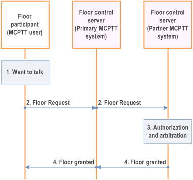
Figure 10.12-1 provides the procedure for media related signalling.
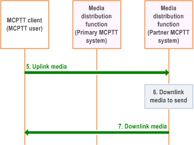
Figure 10.12-2 provide the procedure for the media transmission (directly) between MCPTT UE of the user and the partner MCPTT system.
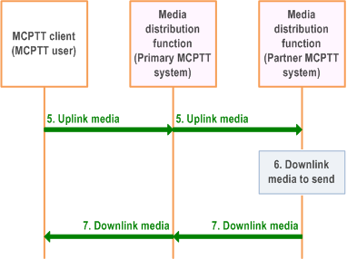
Figure 10.12-3 provides the procedure for the media transmission (via the primary MCPTT system) between MCPTT UE of the user and the partner MCPTT system.
Pre-conditions:
- The MCPTT group is defined in the partner MCPTT system, where the MCPTT client of user receives the MCPTT service.
- An MCPTT group call is set up and active.
- The partner MCPTT system is the group host MCPTT server that is hosting the MCPTT group. The corresponding floor control server manages the media corresponding to the group call.
- Protocol used for signalling of media plane is non-SIP, it can be protocol like RTCP.
- Media related signalling is sent via the primary MCPTT system.
- The path for media between the MCPTT UE and partner MCPTT system has been selected to be sent directly to the partner MCPTT system or via the primary MCPTT system based on PLMN operator's policy.


For media related signalling communication:
Step 1.
For media communication:
An MCPTT user wants to talk.
Step 2.
The floor participant corresponding to the MCPTT user sends a floor request message to floor control server (partner MCPTT system) to get the authorization and/or permission to talk.
Step 3.
The floor control server (partner MCPTT system) performs the authorization and arbitrates between requests that are in contention (i.e., floor control).
Step 4.
If the floor control server (partner MCPTT system) allows the floor participant to talk, a floor granted is provided with permission granted to talk.
Step 5.
The MCPTT client can now send uplink media data to the media distribution function of the MCPTT server (partner MCPTT system).
Step 6.
The media distribution function of the MCPTT server (partner MCPTT system) has downlink media data to transfer.
Step 7.
The media distribution function of the MCPTT server (partner MCPTT system) transfers the downlink media to the MCPTT client of the MCPTT user.
10.13 Location information (on-network) p. 207
The MCPTT system makes use of all of the procedures for location management as specified in TS 23.280, utilising the CSC-14 reference point between the location management client and location management server and the CSC-15 reference point between the MCPTT server and location management server.
- The MC service client is the MCPTT client;
- The MC service server is the MCPTT server;
- The MC service group is the MCPTT group;
- The MC service ID is the MCPTT ID; and
- The MC service group ID is the MCPTT group ID.