Content for TS 23.272 Word version: 17.0.0
1…
4…
5…
5.4…
6…
6.3
6.4…
7…
7.3
7.4…
7.5a…
8…
8.2.4a…
8.3…
8.4…
B…
B.2…
B.2.2…
B.2.3a…
B.2.3a.4…
B.2.4…
B.3…
C…
C.8…
B.2.3a Enhanced CS fallback to 1xRTT Procedure
B.2.3a.1 General
B.2.3a.2 Mobile Originating Call without concurrent PS handover, or with concurrent non-optimised PS handover or optimised idle-mode PS handover
B.2.3a.3 Mobile Originating Call with concurrent optimised PS handover
...
...
B.2.3a Enhanced CS fallback to 1xRTT Procedure |R9| p. 80
B.2.3a.1 General p. 80
Enhanced CS fallback to 1xRTT procedure may be used when the UE indicates its support of this capability to the network. If in addition, the UE also indicates its support of concurrent 1xRTT and HRPD PS session handling, this indication also allows the network to invoke optimised or non-optimised PS handover procedure concurrently with the enhanced CS fallback to 1xRTT procedure.
A network that advertises support for enhanced CS fallback to 1xRTT may also advertise support for UEs with dual 1xRTT and E-UTRAN receiver/transmitter configuration. In such networks, UEs that support enhanced CS fallback to 1xRTT for dual receiver/transmitter configuration may switch off their 1xRTT receiver/transmitter while camped in E-UTRAN and register in the 1xRTT domain via the S102 tunnel. A network advertising these capabilities does not suspend the EPS bearers for mobile originated or mobile terminated 1x CS calls for such UEs. Concurrent enhanced CS fallback to 1xRTT and PS handover to HRPD is not performed for UEs that support enhanced CS fallback to 1xRTT for dual receiver/transmitter configuration.
If enhanced CS fallback to 1xRTT procedure is not used by the network (i.e., not supported or not configured), the network uses RRC connection release with redirection as specified in clause B.2.2 and clause B.2.3.
B.2.3a.2 Mobile Originating Call without concurrent PS handover, or with concurrent non-optimised PS handover or optimised idle-mode PS handover p. 81
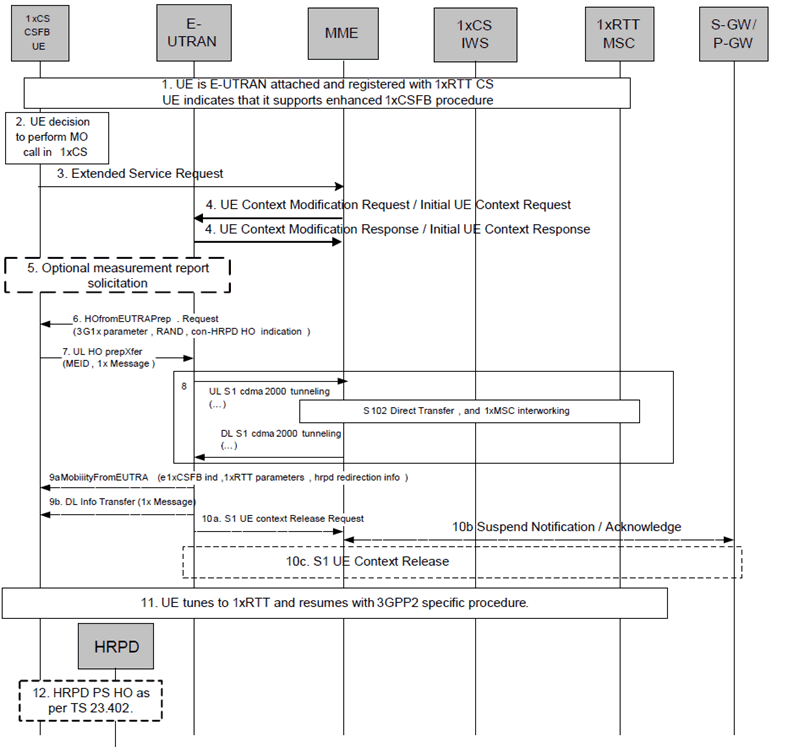
The following Figure describes the mobile originating call procedures for the enhanced CS Fallback to 1xRTT with concurrent non-optimised PS handover or optimised idle-mode PS handover, or without concurrent PS handover, in the normal case. Clause B.2.3b describes the procedure when the procedure is rejected by the MME.

Figure B.2.3a.2-1: Enhanced CS fallback to 1xRTT MO Call with no PS handover, or with concurrent non-optimised PS handover or optimised idle-mode PS handover
(⇒ copy of original 3GPP image)
(⇒ copy of original 3GPP image)
Step 1.
UE is E-UTRAN attached and registered with 1xRTT CS as defined in clause B.2.1.1 with enhanced CS fallback to 1xRTT capability indication to E-UTRAN. The UE may also indicate that it supports concurrent 1xRTT and HRPD capability. The UE may also be pre-registered with HRPD access using procedures defined in clause 9.3.1 of TS 23.402. The UE may also indicate support of enhanced CS Fallback to 1xRTT for dual receiver/transmitter configuration to E-UTRAN.
Step 2.
UE makes a decision to perform a mobile originated CS call.
Step 3.
UE sends an Extended Service Request for mobile originating 1xCS fallback to the MME.
Step 4.
For a UE in active mode, MME sends UE Context Modification Request (CS Fallback Indicator) to E-UTRAN. CS Fallback Indicator indicates to the E-UTRAN to move the UE to 1xRTT.
E-UTRAN responds with UE Context Modification Response.
For a UE in idle mode, MME sends Initial UE Context Request (CS Fallback Indicator) to E-UTRAN. CS Fallback Indicator indicates to the E-UTRAN to move the UE to 1xRTT. E-UTRAN responds with Initial UE Context Response.
If MME determines the CS Fallback procedure needs priority handling based on MPS CS priority in the UE's EPS subscription and/or the high priority access indication that the eNodeB includes in the S1AP message in step 3, it sets priority indication as well as CS Fallback indicator in the S1AP message to the eNodeB. According to operator policy the MME may use CS priority indicator to verify the priority handling of the CS Fallback procedure, in the case high priority access indication is received in the S1-AP message. The E-UTRAN, in congestion conditions, provides preferential treatment for this call in the subsequent steps. Also, the E-UTRAN shall not trigger enhanced 1xCSFB with concurrent optimized PS handover to HRPD access.
Step 5.
E-UTRAN may optionally solicit a 1xRTT measurement report from the UE to determine the target 1xRTT cell to which the CS Fallback will be performed.
If the network supports PS handover procedure to HRPD then E-UTRAN may optionally solicit an HRPD measurement report from the UE to determine whether the target HRPD candidates exist or not.
Step 6.
E-UTRAN sends a HandoverFromE-UTRAPreparation Request message to the UE to start the enhanced 1xCS fallback procedure. It includes 3G1x Overhead Parameters and RAND value. This message also includes an indication that concurrent HRPD handover preparation is not required.
When both the network and the UE support enhanced CS Fallback to 1xRTT for dual receiver/transmitter configuration, the E-UTRAN may after Step 4 decide, e.g. due to RF conditions, to direct the UE to turn on its second radio to 1xRTT and retry the 1xCS call directly on the 1xRTT access network. For this case, the E-UTRAN in the HandoverFromE-UTRAPreparation Request message includes a redirection indicator along with optional redirection information. The procedure stops after this step and the UE tunes its 1x radio and retries its 1x call in 1xRTT while still receiving/transmitting data on E-UTRAN.
Step 7.
The UE initiates signalling for establishment of the CS access leg by sending UL HandoverPreparation Transfer message which contains the 1xRTT Origination message with called party number.
Step 8.
Messages between MME and 1xIWS are tunnelled using the S102 interface. The 1xRTT MSC initiates the call with the called party number carried in the 1xRTT Origination message.
Step 9.
The E-UTRAN performs either Step 9a or Step 9b. Step 9b is only performed when both the E-UTRAN and UE support enhanced 1x CS fallback to 1xRTT for dual receiver/transmitter configuration.
Step 9a.
The E-UTRAN sends Mobility from EUTRA Command to the UE with indication that this is for enhanced 1x CS Fallback operation, 1xRTT related information, and optionally the HRPD redirection information. The 1xRTT information contains 1xRTT messages related to 1x channel assignment and cause the UE to tune to and acquire this 1x channel. This is perceived by the UE as a Handover Command message to 1xRTT.
Step 9b.
- If the network does not support PS handover procedure to HRPD or if no target HRPD candidates exist then E-UTRAN shall release the S1 UE context (see step 10a/b) after executing the enhanced CS fallback to 1xRTT procedure.
- For either concurrent non-optimised PS handover procedure or optimised idle-mode PS handover procedure along with enhanced CS fallback to 1xRTT, E-UTRAN may also redirect the UE to HRPD as part of this procedure. This is indicated by the HRPD redirection information in the Mobility from EUTRA Command.
The E-UTRAN sends DL information transfer message, with the embedded 1x message indicating 1xRTT preparation success to the UE. Steps 10 and 12 are not performed in this case.
Step 10a/b/c.
If PS handover procedure is not performed then E-UTRAN sends an S1 UE Context Release Request (Cause) message to the MME. Cause indicates that the S1 UE Context Release was caused by CS fallback to 1xRTT. The S1-U bearers are released and the MME starts the preservation and suspension of non-GBR bearers and the deactivation of GBR bearers towards S-GW and P-GW(s). The MME sets the UE context to suspended status.
Step 11.
UE tunes to the 1xRTT radio access network and performs 1xchannel acquisition with the 1xRTT CS access (e.g. 1xRTT BSS). A UE supporting enhanced 1xCSFB to 1xRTT for dual receiver/transmitter configuration continues to receive/transmit data on E-UTRAN.
Step 12.
UE and Network follow the appropriate procedure for handling non-optimised PS handover procedure or optimised idle-mode PS handover as defined in TS 23.402 if performed. S1 UE Context release procedure is as specified in clause 8.2.2 of TS 23.402 for non-optimised PS handover or clause 9.4 of TS 23.402 for optimised idle-mode PS handover. This step occurs in parallel with step 11.
B.2.3a.3 Mobile Originating Call with concurrent optimised PS handover p. 84
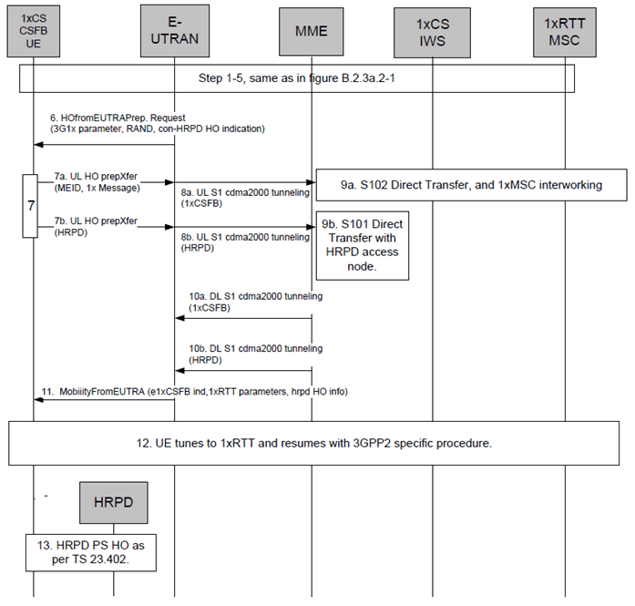
The following Figure describes the mobile originating call procedures for the enhanced CS Fallback procedure to 1xRTT with concurrent optimised PS handover, in the normal case. Clause B.2.3b describes the procedure when the procedure is rejected by the MME. This procedure is not executed for mobile originated priority 1x CS Fallback. This procedure is not performed when both the network and the UE support enhanced CS Fallback to 1xRTT for dual receiver/transmitter configuration.

Figure B.2.3a.3-1: Enhanced CS fallback to 1xRTT MO Call with concurrent optimised PS handover
(⇒ copy of original 3GPP image)
(⇒ copy of original 3GPP image)
Step 1-5.
Same as steps 1-5 in Figure B.2.3a.2-1. The UE indicates that it supports enhanced CS fallback to 1xRTT procedure and concurrent 1xRTT and HRPD capability.
Step 6.
E-UTRAN sends an Handover From E-UTRA Preparation Request message to the UE to start the enhanced 1xCS fallback procedure. It includes 3G1x Overhead Parameters and RAND value. This message also includes an indication that concurrent HRPD handover preparation is required.
Step 7.
UE starts the enhanced 1xCS fallback and optimised PS handover messages (7a, 7b) in a sequential manner. Step 7a contains the 1xRTT Origination message with called party number.
Step 8a, 9a, 10a, and 8b, 9b, 10b.
MME treats the enhanced 1xCS fallback and HRPD PS handover procedure independently (i.e. MME does not link the HRPD message and 1xCS fallback message together).
8a, 9a, 10a is same as shown in step 8 in Figure B.2.3a.2-1
8b, 9b, 10b are messages/procedure for optimised E-UTRAN to HRPD handover procedure as defined in clause 9.3.2 of TS 23.402.
Step 11.
The E-UTRAN sends Mobility from EUTRA Command to the UE with indication that this is for enhanced 1x CS Fallback operation including the 1xRTT message and the HRPD message received over the S102 and S101 tunnels.
If handover preparation to HRPD is successful but preparation failure message in received from the 1xRTT CS network via the S102 tunnel, the message for 1xRTT preparation failure indication is sent to the UE as part of the Mobility from EUTRA Command. If handover to HRPD is successful and the eNodeB times out waiting for preparation completion message from 1xRTT, the E-UTRAN sends a Mobility from EUTRA command with only the HPRD message included. In the case that the preparation to HRPD failed but 1xRTT is successful, E-UTRAN may optionally include HRPD redirection info as part of the Mobility from EUTRA Command.
In case preparation on 1xRTT and HRPD failed with explicit failure messages received on S102 and S01 tunnels, the E-UTRAN forwards the received failure messages as DL Information transfers. In this case, steps 12 and 13 are skipped.
Step 12.
UE retunes to the 1xRTT radio access network and performs 1x channel acquisition with the 1xRTT CS access (e.g. 1xRTT BSS), see clause 6.1.3 of TS 23.216.
Step 13.
UE and network follow the optimised E-UTRAN to HRPD handover procedure. UE context release procedure follows the optimised E-UTRAN to HRPD handover procedure as defined in clause 9.3.2 of TS 23.402. This step occurs in parallel with step 12.