Content for TS 23.272 Word version: 17.0.0
1…
4…
5…
5.4…
6…
6.3
6.4…
7…
7.3
7.4…
7.5a…
8…
8.2.4a…
8.3…
8.4…
B…
B.2…
B.2.2…
B.2.3a…
B.2.3a.4…
B.2.4…
B.3…
C…
C.8…
6 Mobile Originating Call
6.1 General
6.2 Mobile Originating call in Active Mode - PS HO supported
...
...
6 Mobile Originating Call p. 28
6.1 General p. 28
This clause describes the mobile originating call procedures for the CS Fallback in EPS.
6.2 Mobile Originating call in Active Mode - PS HO supported p. 29
This flow may be executed when the eNodeB knows that both the UE and the network support PS HO, in the normal case. Clause 6.6 describes the procedure when the procedure is rejected by the MME.
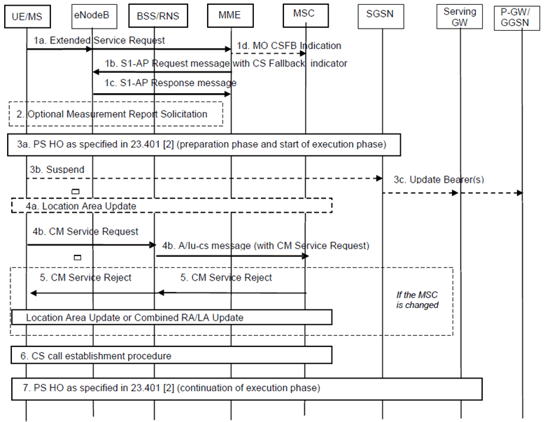
Step 1a.
If the UE remains on UTRAN/GERAN after the CS voice call is terminated the UE performs normal mobility management procedures as defined in TS 23.060 and TS 24.008.
The UE sends an Extended Service Request for mobile originating CS fallback to MME. Extended Service Request message is encapsulated in RRC and S1 AP messages. The UE only transmits this request if it is attached to CS domain (with a combined EPS/IMSI Attach).
Step 1b.
The MME sends an S1 AP UE Context Modification Request (CS Fallback Indicator, LAI) message to eNodeB. This message indicates to the eNodeB that the UE should be moved to UTRAN/GERAN. The registered PLMN for CS domain is identified by the PLMN ID included in the LAI, which is allocated by the MME.
If MME determines the CS Fallback procedure needs priority handling based on MPS CS Priority in the UE's EPS subscription or because the call is an emergency call, it also sets priority indication, i.e. "CSFB High Priority", in the S1AP message to the eNodeB as specified in TS 36.413. In the case of emergency call, the MME also requests the eNodeB to inhibit roaming and access restrictions via the Additional CS Fallback Indicator as specified in TS 36.413.
Step 1c.
The eNodeB shall reply with S1-AP UE Context Modification Response message.
Step 1d.
If configured to support the return to the last used PLMN after CSFB, the MME sends a MO CSFB indication via SGs to the MSC in order to indicate that the CM service request message, as described in step 4b in this clause , is due to the CSFB via CS MO call.
Step 2.
The eNodeB may optionally solicit a measurement report from the UE to determine the target GERAN/UTRAN cell to which PS handover will be performed.
Step 3a.
The eNodeB triggers PS handover to a GERAN/UTRAN neighbour cell by sending a Handover Required message to the MME. The eNodeB selects the target PS handover cell considering the PLMN ID and possibly the LAC for CS domain provided by the MME in step 1b.
If the eNB is a HeNB, the HeNB should perform step 3 through step 6 of clause 6.3 instead of PS HO if the HeNB detects that the UE has only LIPA PDN Connections. CSFB will not be completed successfully when PS HO is performed if the UE has only LIPA PDN Connections as PS HO would result in the MME detaching the UE.
In the following an inter-RAT handover from E-UTRAN to UTRAN or GERAN as specified in TS 23.401 begins. The eNodeB indicates in the Source RNC to Target RNC Transparent container that PS handover was triggered due to CSFB. The eNodeB also indicates whether CSFB was triggered for emergency or priority call handling purpose. If the network supports a priority call handling, the eNodeB may forward the priority indication to the target GERAN/UTRAN in the Source to Target Transparent Container, and the target GERAN/UTRAN allocates radio bearer resources taking received priority indication take into account. As part of this handover, the UE receives a HO from E-UTRAN Command and tries to connect to a cell in the target RAT. The HO from E-UTRAN Command may contain a CS Fallback Indicator which indicates to UE that the handover is triggered due to a CS fallback request. If the HO from E-UTRAN Command contains a CS Fallback Indicator and the UE fails to establish connection to the target RAT, then the UE considers that CS fallback has failed. Service Request procedure is considered to be successfully completed when PS Handover procedure is completed successfully.
When the UE arrives at the target cell, if the target RAT is UTRAN, the UE establishes the radio signalling connection by sending an RRC Initial Direct Transfer message as specified in TS 25.331 that contains a NAS message. The CN Domain Indicator is set to "CS" in the Initial Direct Transfer message.
If the target RAT is GERAN A/Gb mode: The UE establishes a radio signalling connection by using the procedures specified in TS 44.018 (i.e. UE requests and is assigned a dedicated channel where it sends a SABM containing a NAS message to the BSS and the BSS responds by sending a UA). Upon receiving the SABM (containing the NAS message) the BSS sends a COMPLETE LAYER 3 INFORMATION message (containing the NAS message) to the MSC which indicates CS resources have been allocated in the GERAN cell. If both the UE and the target cell support enhanced CS establishment in DTM (indicated by GERAN system information included within the HO from E-UTRAN Command) a RR connection may be established while in packet transfer mode without release of the packet resources, see TS 43.055. After the establishment of the main signalling link as described in TS 44.018 the UE enters either Dual Transfer Mode or Dedicated Mode.
Step 3b.
If the target RAT is GERAN and the UE has entered Dedicated Mode, the UE starts the Suspend procedure (see TS 44.018) unless both the UE and the Target cell support DTM in which case TBF re-establishment may be performed.
Step 3c.
A Gn/Gp-SGSN that receives the Suspend message from the UE follows the Suspend procedure specified in clause 16.2.1.1.1 of TS 23.060.
An S4-SGSN that receives the Suspend message from the UE follows the Suspend procedure specified in TS 23.060. The S4-SGSN deactivates GBR bearers towards S-GW and P-GW(s) by initiating MS-and SGSN Initiated Bearer Deactivation procedure as specified in TS 23.060, and starts the preservation and suspension of non-GBR bearers by sending Suspend Notification message to the S-GW. The S-GW releases all RNC related information (address and TEIDs) for the UE if Direct Tunnel is established, and sends Suspend Notification message to the P-GW(s). The SGSN stores in the UE context that UE is in suspended status. All the preserved non-GBR bearers are marked as suspended status in the S-GW and P-GW(s). The P-GW should discard packets if received for the suspended UE.
Step 4a.
If the LA of the new cell is different from the one stored in the UE (which is received as part of Combined Attach/TAU procedure in E-UTRAN), the UE shall initiate a Location Area Update procedure as follows:
Step 4b.
- if the network is operating in NMO-I (Network Modes of Operation), the UE shall initiate a separate Location Area Update before initiating the RAU procedure instead of a Combined RA/LA Update procedure (to speed up the CSFB procedure); or
- if the network is operating in NMO-II, the UE shall initiate a Location Area Update before initiating the RAU procedure required for PS handover.
The UE sends a CM Service Request to the MSC. The UE shall indicate to the MSC that this is an originating call establishment as a result of CSFB by including the "CSMO" flag.
Step 5.
If the UE is not registered in the MSC serving the 2G/3G target cell or the UE is not allowed in the LA, the MSC shall reject the CM service request, if implicit location update is not performed. The CM Service Reject shall trigger the UE to perform a Location Area Update or a Combined RA/LA Update procedure as specified in TS 23.060 for the different Network Modes of Operation (NMO).
When different from the serving MSC, the target MSC derives the Last Used LTE PLMN from the MAP Send Identification message received from the serving MSC/VLR during the Location Area Update procedure.
Step 6.
The UE initiates the CS call establishment procedure and the UE shall include the CSMO flag in the CM Service Request to the MSC.
Step 7.
The UE performs any remaining steps of the inter-RAT handover from E-UTRAN to UTRAN or GERAN as specified in TS 23.401.
![]()
![]()
![]()