Content for TS 23.272 Word version: 17.0.0
1…
4…
5…
5.4…
6…
6.3
6.4…
7…
7.3
7.4…
7.5a…
8…
8.2.4a…
8.3…
8.4…
B…
B.2…
B.2.2…
B.2.3a…
B.2.3a.4…
B.2.4…
B.3…
C…
C.8…
8 Other CS Services
8.1 General
8.2 Short Message Service (SMS)
8.2.1 General
8.2.2 Mobile originating SMS in Idle Mode
8.2.3 Mobile originating SMS in Active Mode
8.2.3a Multiple Mobile originating SMSs
8.2.4 Mobile terminating SMS in idle mode
...
...
8 Other CS Services p. 54
8.1 General p. 54
The MSC handles the timers, queuing and retransmission for sending the SGsAP-PAGING-REQUEST message on the SGs interface in the same way that it handles the sending of a PAGING message on the A or Iu interface. As a consequence, the MME and (if ISR is active) the SGSN shall not implement local retransmission schemes for this paging.
8.2 Short Message Service (SMS) p. 54
8.2.1 General p. 54
The procedures for SMS in this specification apply only if the UE is EPS/IMSI attached and the Non Access Stratum signalling based SMS transfer is chosen by the UE and/or the home PLMN for delivering short messages.
This clause describes both the mobile originating and mobile terminating SMS over SGs procedures in EPS. SMS support is based on the connectionless SGs reference point between the MME and the MSC Server and use of NAS signalling between the UE and the MME, i.e. no CS Fallback is performed for SMS.
This clause also describes the SMS procedures between the UE and the MME for UEs that use only PS and SMS services but no CS Fallback via GERAN and/or UTRAN.
The SMS protocol entities are reused from the existing MS/UE and MSC implementations. This means that the SMS over SGs procedures reuse the different protocol layers as defined in TS 23.040.
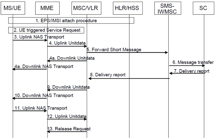
8.2.2 Mobile originating SMS in Idle Mode p. 54
The following sequence flow shows the delivery of mobile originating SMS in idle mode. The message flows between the ME/UE and MSC/VLR are also broadly applicable to the Memory Available Notification.

Step 1.
The combined EPS/IMSI attach procedure as described in clause 5.2 has been performed earlier.
Step 2.
A mobile originating SMS is triggered and the MS/UE is in idle mode. The MS/UE initiates the UE triggered Service Request procedure, which is defined in TS 23.401. The UE indicates its S TMSI in the RRC signalling. If the UE and the MME accept to use Control Plane CIoT EPS Optimisation, then to enable SMS transfer the Service Request procedures defined in TS 23.401 are not used for MO SMS, but instead UE and MME shall be using Control Plane CIoT EPS Optimisation.
For E-UTRAN, if there is a Service Gap timer running in the MME for the UE and the MME is not waiting for a MT paging response from the UE, the MME rejects the Service Request by discarding any NAS data PDU and sending a Service Reject message to the UE with an appropriate cause. The MME may also provide UE with a Mobility Management Back-off timer set to the remaining value of Service Gap timer (see clause 4.3.17.9 of TS 23.401).
Step 3.
The MS/UE builds the SMS message to be sent as defined in TS 23.040 (i.e. the SMS message consists of CP-DATA/RP-DATA/TPDU/SMS-SUBMIT parts). Following the activation of the Radio Bearers, the SMS message is encapsulated in an NAS message and sent to the MME.
Step 4.
The MME forwards the SMS message to the MSC/VLR in an Uplink Unitdata message. In order to permit the MSC to create an accurate charging record, the MME adds the IMEISV, the local time zone, the Mobile Station Classmark 2, and the UE's current TAI and E CGI.
Step 4a.
The MSC/VLR acknowledges receipt of the SMS to the UE.
Step 5.-8.
These steps are performed as defined in TS 23.040. The SMS message is forwarded to the SC that returns a delivery report message.
Step 9.
The MSC/VLR forwards the received delivery report to the MME associated with the MS/UE in a Downlink Unitdata message.
Step 10.
The MME encapsulates the received delivery report in an NAS message and sends the message to the MS/UE.
Step 11, 12.
The UE acknowledges receipt of the delivery report to the MSC/VLR.
Step 13.
The MSC/VLR indicates to the MME that no more NAS messages need to be tunnelled.
The MME should not use the SGs Release Request message as a trigger for the release of S1 resources.
8.2.3 Mobile originating SMS in Active Mode p. 56
Mobile Originating SMS in active Mode procedure is specified by reusing the Mobile Originating SMS in Idle Mode with the following modification:
- The established signalling connection between the MS/UE and the MME is reused for the transport of the SMS message and the delivery report (i.e. the UE triggered Service Request procedure defined in step 2 is skipped).
8.2.3a Multiple Mobile originating SMSs p. 56
In clause 3.2 of TS 24.011, the simultaneous transmission of more than one MO SMS/notification per domain is prohibited.
If the UE has more than one SMS/notification to send, the subsequent SMS/notification is sent at step 11 of clause 8.2.2 and the acknowledgement of the delivery report for the previous SMS/notification is not sent.
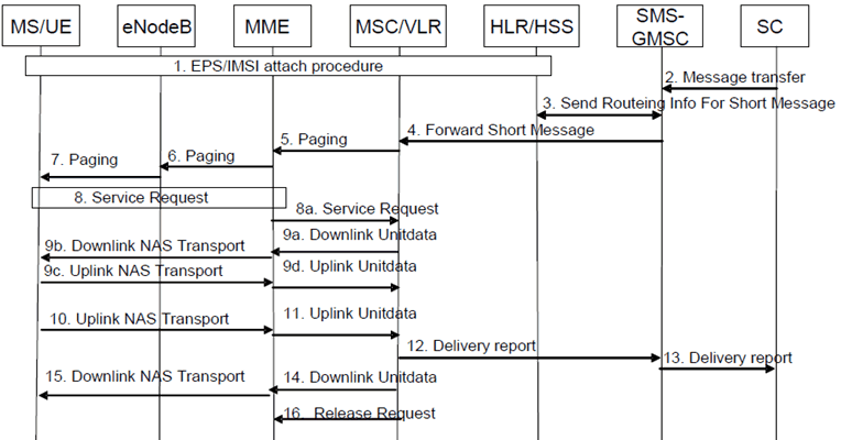
8.2.4 Mobile terminating SMS in idle mode p. 56
The following sequence flow shows the delivery of mobile terminating SMS in idle mode.

Step 1.
The combined EPS/IMSI attach procedure as described in clause 5.2 has been performed.
Step 2 4.
The SC initiates transfer of mobile terminating SMS. The HLR is requested for routing number for SMS services and the SMS message is forwarded to the MSC/VLR where the MS/UE is CS attached.
Step 5.
The MSC/VLR sends a Paging (IMSI, VLR TMSI, Location Information, SMS indicator) message to the MME.
Step 6.
The MME initiates the paging procedure by sending the Paging (as specified in TS 23.401) message to each eNodeB with cells belonging to the tracking area(s) in which the UE is registered. The UE is paged with its S TMSI.
Step 7.
The MS/UE is paged by the eNodeBs.
Step 8.
The UE sends a Service Request message to the MME. The UE indicates its S TMSI in the RRC signalling. The MME sends the S1-AP Initial Context Setup Request message to the eNodeB and the eNodeB establishes the Radio Bearers. If the UE and the MME accept to use Control Plane CIoT EPS Optimisation, then to enable SMS transfer the Service Request procedures defined in TS 23.401 are not used, but instead UE and MME shall be using the Control Plane CIoT EPS Optimisation.
Step 8a.
The MME sends a Service Request message to the MSC. In order to permit the MSC to create an accurate charging record, the MME adds the IMEISV, the local time zone, the Mobile Station Classmark 2, and the UE's current TAI and E CGI.
Step 9a.
The MSC/VLR builds the SMS message to be sent as defined in TS 23.040 (i.e. the SMS message consists of CP DATA/RP DATA/TPDU/SMS DELIVER parts). The MSC/VLR forwards the SMS message to the MME in a Downlink Unitdata message.
Step 9b.
The MME encapsulates the SMS message in a NAS message and sends the message to the MS/UE.
Step 9c, 9d.
The MS/UE acknowledges receipt of the SMS message to the MSC/VLR.
Step 10.
The MS/UE returns a delivery report as defined in TS 23.040. The delivery report is encapsulated in an NAS message and sent to the MME.
Step 11.
The MME forwards the delivery report to the MSC/VLR in an Uplink Unitdata message.
Step 12 13.
These steps are performed as defined in TS 23.040. The delivery report is forwarded to the SC.
Step 14-15.
In parallel to steps 12-13, the MSC/VLR acknowledges receipt of the delivery report to the MS/UE.
Step 16.
The MSC/VLR indicates to the MME that no more NAS messages need to be tunnelled.
The MME should not use the SGs Release Request message as a trigger for the release of S1 resources.