Content for TS 23.256 Word version: 18.2.0
1…
4…
4.2…
4.3…
4.4…
4.5…
5…
5.2.3…
5.2.4…
5.2.5…
5.2.5.3…
5.2.5.4…
5.2.7
5.2.8…
5.2.9…
5.3…
5.4…
5.5…
6…
6.2…
6.3…
6.3.4…
5.5 Broadcast Remote ID
5.5.1 Broadcast Remote ID using PC5
5.5.2 Broadcast Remote ID using MBS
5.5.2.1 Policy/Parameter provisioning
5.5.2.2 Broadcast Remote ID reception via MBS
5.5.2.3 QoS handling
5.5.2.4 MBS service area mapping
5.6 Mechanisms for Detect and Avoid (DAA)
5.6.1 Mechanisms for Detect and Avoid (DAA) based on PC5
5.7 Ground-based DAA for an Area
5.7.1 Functional Description
5.7.2 Procedures
...
...
5.5 Broadcast Remote ID |R18| p. 65
5.5.1 Broadcast Remote ID using PC5 p. 65
Broadcast Remote ID leverages A2X broadcast communication mode as defined in clauses 6.2.2.1.2 and 6.3.3.1, for both UAV UEs that register to the MNO network(s) and UAVs that operate out of coverage.
The content of the messages for BRID is defined according to regional regulations for BRID (e.g. message set of ASTM F3411.19 [13] or ASD-STAN prEN 4709-002 P1 [14]) and optionally according to regional mean of compliance documents.
Authorization and provisioning of policy parameters for A2X communication over PC5 reference point as described in clause 6.2.1.2 is leveraged. Where applicable, an A2X service type indicating Broadcast Remote ID is used.
5.5.2 Broadcast Remote ID using MBS p. 66
5.5.2.1 Policy/Parameter provisioning p. 66
Policy parameters provisioning as described in clause 6.2.1.3 for A2X communication over Uu reference point is leveraged. Where applicable an A2X service type indicating Broadcast Remote ID is used.
5.5.2.2 Broadcast Remote ID reception via MBS p. 66
The A2X Broadcast Remote ID service is identified with a corresponding service type.
The Broadcast Remote ID sent by a UAV UE to an A2X application server identified by A2X service type set to Broadcast Remote ID is as a A2X message routed to UAV UEs via MBS sessions using the mechanisms and procedures described in clause 6.2.2.2.2.
The content of the A2X message is the Broadcast Remote ID, e.g. as defined in ASTM F3411.19 [13] or ASD-STAN prEN 4709-002 P1 [14].
5.5.2.3 QoS handling p. 66
QoS is handled as described in clause 6.2.4.2 for delivery of A2X message over MBS.
5.5.2.4 MBS service area mapping p. 66
Broadcast Remote ID using MBS facilitates procedures and mechanisms for MBS service area mapping for A2X communication with MBS as specified in clause 6.3.4.2.1 in accordance with:
- UE applies to a UAV UE.
5.6 Mechanisms for Detect and Avoid (DAA) |R18| p. 66
5.6.1 Mechanisms for Detect and Avoid (DAA) based on PC5 p. 66
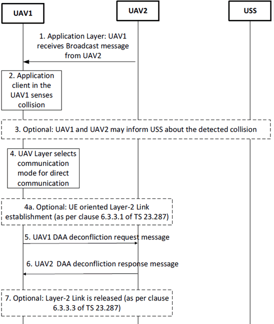
DAA leverages procedures and mechanisms as defined for A2X in clause 6. This includes the corresponding references to TS 23.287 below.
The detection and deconfliction of potential collisions between UAVs is locally performed between UAVs using direct UAV to UAV communication over PC5. The USS may be informed of the potential collision situation.
Deconflicting policy which indicates the communication mode (unicast or broadcast) used for deconflicting for A2X is defined in clause 6.2.1.2.1.
Authorization and provisioning of policy parameters for A2X communication over PC5 reference point as described in clause 6.2.1.2 is leveraged.

Step 1.
The steps 5 and 6 are then exchanged over the established unicast link.
UAV1 receives broadcast messages from UAV2 in PC5-U messages, that may include application layer DAA payload, e.g. CAA-level UAV ID, velocity, heading direction, position.
Step 2.
UAV1 passes the DAA payload to the upper layer. The application layer detects a conflict, based on the broadcast messages received from UAV2, e.g. by comparing it with its own trajectory and location. If the application layer in the UAV1 detects a potential collision situation, it initiates a collision avoidance/conflict resolution procedure with UAV2.
Step 3.
Optionally, UAV1 may inform its own USS about the detected potential collision by including peer UAV2 ID(s).
Step 4.
UAV1 selects a communication mode (broadcast or unicast) for DAA deconfliction based on the input received from the application layer and A2X Policy. If unicast deconfliction mode is selected then step 4a is executed, otherwise, messages in steps 5 and 6 are exchanged using broadcast mode as defined in clause 6.3.1 of TS 23.287.
Step 4a.
Optional: If unicast deconfliction mode is selected, then UAV1 triggers Layer-2 link establishment for unicast communication with UAV2 by applying to A2X the procedure defined in clause 6.3.3.1 of TS 23.287 with the following clarifications:
- If the Target User Info is included in the Direct Communication Request message, Application layer ID of the target UE (UAV2) can be the one retrieved from the step 1, e.g. CAA-level UAV ID.
- If the Target User Info is not included in the Direct Communication Request message, the UEs that are interested in using the announced A2X service type(s) over a PC5 unicast link with UAV1 responds by establishing the security with the UAV1.
Step 5.
UAV1 sends to UAV2 a DAA deconfliction message, e.g. deconfliction request message which may include collision detection alert, its CAA-level UAV IDs and the one(s) from other detected conflicting UAV(s), and deconflicting specific parameters (e.g. trajectory correction information to avoid collision).
Step 6.
UAV2 replies to provide agreed DAA deconflicting policy, its updated trajectory and other info, e.g. message deconfliction status response, conflict resolved alert, CAA-level UAV IDs of participating UAVs from the receiving UAV.
Subsequent messages may be exchanged between UAVs until traffic conflict resolution is reached (e.g. for mutual position/trajectory monitoring) based on application layer mechanisms.
Step 7.
After the successful traffic conflict resolution, if unicast deconfliction mode was selected, the UAV1 triggers Layer-2 link release procedure as described in clause 6.3.3.3 of TS 23.287.
5.7 Ground-based DAA for an Area |R18| p. 68
5.7.1 Functional Description p. 68
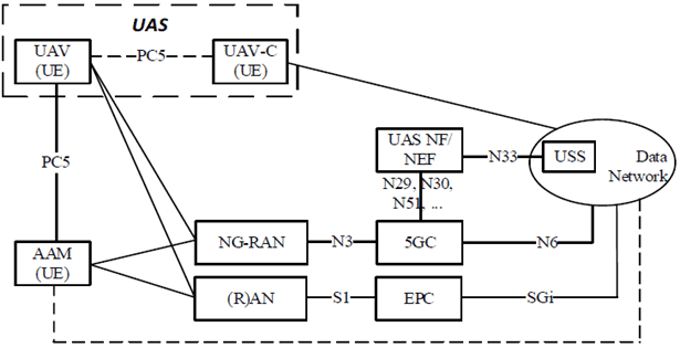
This clause provides a network-assisted (ground based) DAA mechanism. It is applicable for a specific area, such as a stadium or arena where UAVs are used e.g. for filming an event. It is based on a ground-based entity, Area Airspace Manager (AAM), that is able to detect UAVs in the specific area and provide local steering policies to the individual UASs in order to avoid the UAVs crashing into each other or different structures etc. The policy may e.g. include allowed flying zones and positions allowed for the specific UAV. The policy may also apply to a specific outdoor area, e.g. an event, where specific measures to avoid collision between drones are established locally.
The high-level principles of the network-assisted (ground based) DAA are:
- The arena/area has a ground-based entity Area Airspace Manager (AAM). The AAM includes one or more UEs enabled for use of PC5. The AAM may also have a direct connection to the Data Network.
- For the applicable airspace of the area/arena the AAM defines individually adapted local collision avoidance rules for correspondingly located UAVs.
- Provisioning of AAM local collision avoidance rules to a UAV/UE must comply with the policies for PC5 operations received from the 5GC or being preconfigured in the UE.
- Detected UAVs are identified by their coordinates and by the Remote ID as retrieved by Broadcast Remote ID (BRID) or Network Remote ID (NRID) mechanisms dependent on the method used by the UAV.
- Based on the retrieved Remote ID, the AAM activates PC5 communication with each detected UAV by triggering establishment of an A2X PC5 unicast link based on procedures described in clause 6 using the UAV's Remote-ID as Application-Layer-ID (i.e. Target User Info) in the Direct Communication Request message.
- The default destination Layer-2 ID to be used for initial signalling to establish a unicast connection for the A2X service.
- Parameters for Groupcast are not applicable.
- The AAM uses PC5 unicast link to provide each UAV present in the arena/area with local DAA policies as user traffic.
- A UAV that receives local collision avoidance related policies from the AAM over PC5 may forward the policies to its UAV-C so that the UAV-C can steer the UAV accordingly by use of C2 communication (e.g. over Uu, PC5, or other means) in order to enforce the local policies and avoid collisions.

5.7.2 Procedures p. 70

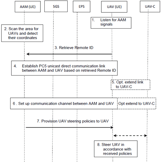
Figure 5.7.2-1: High-level procedure for Ground-based DAA for an Area
(⇒ copy of original 3GPP image)
(⇒ copy of original 3GPP image)
Ground-based DAA for an area leverages the procedures and mechanisms defined for A2X. Any references to TS 23.287 made in this clause shall be interpreted in accordance with corresponding definitions and descriptions for A2X in clause 6.
Prerequisites:
The AAM/UE and the UAVs/UEs are configured to use an A2X service for Ground-based DAA for an area.
Step 1.
The UAVs/UEs listens for signals on the correspondingly destination Layer-2 ID configured for the used service type in accordance with clause 6.3.3.1 of TS 23.287 (Figure 6.3.3.1-1 step 1).
Step 2.
The AAM can scan the airspace over the area/arena for UAVs, e.g. by making use of upward pointing radars and cameras etc. For each detected UAV it determines the coordinates.
Step 3.
The AAM retrieves for each detected UAV the corresponding Remote-ID using the method applicable for the specific UAV. Methods which may be used includes broadcast of Remote-ID via PC5, WiFi and Bluetooth and also Network Remote ID.
How this is done is out of the 3GPP scope.
Step 4.
For each detected UAV/UE the AAM establishes a PC5 direct communication link with the discovered UAV for AAM to UAS interaction by performing the Layer-2 link establishment procedure as described when Target User Info is included in clause 6.3.3.1 of TS 23.287 (Fig 6.3.3.1-1 step 2, 3 4a, 5a and 6). The AAM application layer provides a service type indicating the A2X service "Ground-based DAA for an area" and the retrieved Remote-ID as target UE's Application Layer ID. As a result of this procedure a PC5 unicast direct communication link enabling bidirectional data exchange is set up between the application layer in the AAM and the UAV application layer of the UAV/UE having the specified Remote-ID.
Step 5.
Optionally the UAV/UE may, when the PC5 unicast direct communication link between the AAM and the UAV/UE has been set up for NR, activate a corresponding bidirectional communication connection extending the link from the UAV to the UAV-C using the specific communication technology used for C2 communication (may e.g. be LR Wi-Fi or PC5). This enables packets received on the link (i.e. from the AAM) to be forwarded to the UAV-C and packets received from the UAV-C to be forwarded on the link (i.e. towards the AAM). Implementation aspects for this step are out of scope for 3GPP.
Step 6.
Using the PC5 unicast direct communication link the AAM and the UAV establishes a bidirectional communication channel for exchange of messages. Optionally this channel can be extended to involve the UAV-C using the bi-directional tunnel. The protocol and implementation aspects for this step are out of scope for 3GPP.
Step 7.
The AAM provides the determined steering policy to the specific UAV using the activated communication channel. Optionally it can be forwarded to the UAV-C which can return corresponding C2 commands. Protocols, semantics and syntax for handling this are application specific and out of 3GPP scope.
Step 8.
The UAV is steered to avoid collisions in accordance with received policy and using mechanisms that are out of scope for 3GPP.