Content for TR 22.804 Word version: 16.3.0
4 Overview
4.1 Background
4.2 Vertical Domains
4.3 Automation
4.3.1 Data flows in automation
4.3.2 Communication in automation
...
...
4 Overview p. 21
4.1 Background p. 21
Clause 4 serves two main purposes. One, in Clause 4.2, it discusses the concept of a vertical domain and it provides an overview of the vertical domains addressed in the present document. Two, in Clause 4.3, it provides a short overview of salient concepts developed in automation research and standardisation. In Clause 4.3.1 automation control paradigms and related data flows are discussed. In Clause 4.3.2, models for describing communication in automation are introduced, and the introduced concepts and parameters are mapped onto 5G concepts. In Clause 4.3.3, the paramount automation system attribute-i.e. dependability-is discussed and implications for 5G communication systems are identified. In Clause 4.3.4 these dependability attributes are described from a 5G communication service perspective and potential parameters for describing dependable communication services, monitoring services, location services, and clock synchronisation services are introduced.
4.2 Vertical Domains p. 21
A vertical domain is a particular industry or group of enterprises in which similar products or services are developed, produced, and provided.
The vertical domains addressed in the present document are
- rail-bound mass transit;
- building automation;
- factory of the future;
- eHealth;
- smart city;
- electric-power distribution;
- central power generation;
- programme making and special events; and
- smart agriculture.
4.3 Automation p. 22
4.3.1 Data flows in automation p. 22
4.3.1.1 Introduction p. 22
The term automation stands for the control of processes, devices, or systems in vertical domains by automatic means [10]. Note that a process always includes physical entities and their attributes. By providing particular input to a process, one tries to generate a particular output (see Figure 4.3.1.1-1).
![Copy of original 3GPP image for 3GPP TS 22.804, Fig. 4.3.1.1-1: Process to be controlled [10]. Note that the process always has a physical component](../img/tinv-22-804-4.3.1.1-1.gif)
Figure 4.3.1.1-1: Process to be controlled [10]. Note that the process always has a physical component
(⇒ copy of original 3GPP image)
(⇒ copy of original 3GPP image)
Examples for such processes are chemical processes in the chemical industry, the control of subways, and factory automation with industrial robots. Example (1): the process in question is a chemical reaction and the input is heat; the yield of the chemical reaction, i.e., the output, varies with said heat. Example (2): for a subway, the input can be electrical energy, the process the acceleration of the subway, and the output reaching the cruising velocity of the subway.
The technology related to automation is referred to as operational technology, which "is hardware and software that detects or causes a change through the direct monitoring and/or control of physical devices, processes and events in the enterprise." [12]. An overview of operational-technology devices can be found elsewhere in the literature [11]. The last decade has seen an increased integration of operational and information technology [14]. Automation technology can be used in private settings such as factories, but it is also used in critical infrastructure such as the electricity grid, civil aviation, public transport, etc. [13].
Clause 4.3.1.2 introduces the main type of systems used in automation, i.e. control systems. Clause 4.3.1.3 introduces the most common activity patterns of control systems. Clause 4.3.1.4 discusses the communication attributes of an automation system. Finally, Clause 4.3.1.5 presents the communication patterns entailed by automation systems.
4.3.1.2 Control systems p. 22
As outlined in Clause 4.3.1.1, automation is about controlling processes by aid of automated means. This objective is accomplished by the use of control systems. "A control system is an interconnection of components forming a system configuration that will provide a desired [process] response." [10].
Four main control functions can be distinguished [11]:
- measure: obtain values from sensors and feed these values as input to a process and/or provide these values as output, for instance to a human user;
- compare: evaluate measured values and compare to process design values;
- compute: calculate, for instance, current error, historic error, future error etc.;
- correct or control: adjust the process.
- sensor: device capable of measuring various physical properties;
- transmitter: device that converts measurements from a sensor and sends the signal;
- controller: provides the logic and control instructions for the process;
- actuator: changes the state of the environment; here the process.
4.3.1.3 Activity patterns in automation p. 23
4.3.1.3.1 Open-loop control p. 23
The salient aspect of open-loop control is the lack of output control; when providing desired output responses to an actuator, it is assumed that the output of the influenced process is predetermined and within an acceptable range. Figure 4.3.1.3.1-1 depicts an open-loop control system.
![Copy of original 3GPP image for 3GPP TS 22.804, Fig. 4.3.1.3.1-1: Open-loop control system [10]](../img/tinv-22-804-4.3.1.3.1-1.gif)
This kind of control loop works if the influences of the environment on process and actuator are negligible. Also, this kind of control is applied in case unwanted output can be tolerated. For instance, the damage done by an electric toaster (open-loop control system) by slightly burning a slice of bread is usually assumed to be negligible. In this example, the desired output response is the crispiness of the toasted bread. The response can, for instance, be chosen by turning a dial on the toaster. The actuator is the heater in the toaster. The dial sets a certain energy level and/or toasting time. When activated, the heater generates heat, which increases the crispiness of the inserted slice of bread over time. This is the process. The output is the toast itself.
4.3.1.3.2 Closed-Loop Control p. 23
Closed-loop control enables the manipulation of processes even if the environment influences the process or the performance of the actuator changes over time. This type of control is realised by sensing the process output and by feeding these measurements back into a controller. Figure 4.3.1.3.2-1 depicts such a system.
![Copy of original 3GPP image for 3GPP TS 22.804, Fig. 4.3.1.3.2-1: Multi-variable closed-loop control system [10]](../img/tinv-22-804-4.3.1.3.2-1.gif)
"In contrast to an open-loop control system, a closed-loop control system utilizes [measurements] of the actual output to compare the actual output with the desired output response." [10]. "An example of a closed-loop control system is a person steering an automobile (assuming his or her eyes are open) by looking at the auto's location on the road and making the appropriate adjustments." [10].
4.3.1.3.3 Sequence Control p. 24
Sequence control may either step through a fixed sequence or it employs logic that performs different actions based on various system states and system input [10][11]. Sequence control can be seen as an extension of both open-loop and closed-loop control, but instead of achieving only one output instance, an entire sequence of output instances can be produced. An example of sequence control is controlling an elevator. Based on at what floor it currently resides, to what floor it is summoned, and to what floor it is directed, different kinds of control actions and actuations are taken. Note that although the name "sequence control" seems to imply a pre-programmed sequence of desired output responses, the elevator example shows that event-based control can also be realised with sequence control.
4.3.1.3.3A Batch control p. 24
Batch processes lead to the production of finite quantities of material (batches) by subjecting input materials to a defined order of processing actions by use of one or more pieces of equipment [70]. The product produced by a batch process is called a batch. Batch processes are discontinuous processes. Batch processes are neither discrete nor continuous; however, they have characteristics of both.
4.3.1.4 Communication attributes p. 24
4.3.1.4.1 Introduction p. 24
Communication in automation can be characterised by two main attributes: periodicity and determinism.
4.3.1.4.2 Periodicity p. 24
In terms of periodicity, it is possible to send messages periodically or aperiodically.
Periodically means that a transmission interval is repeated. For example, a transmission occurs every 15 ms. Reasons for a periodical transmission can be the periodic update of a position or the repeated monitoring of a characteristic parameter. Note that a transmission of a temperature every 15 minutes is a periodical transmission. However, most periodic intervals in communication for automation are rather short. The transmission is started once and continuous unless a stop command is provided.
An a-periodical transmission is, for example, a transmission which is triggered instantaneously by an event, i.e. events are the trigger of the transmission. Events are defined by the control system or by the user. Example events are:
- Process events: events that come from the process when thresholds are exceeded or fallen below, e.g., temperature, pressure, level, etc.
- Diagnostic events: events that indicate malfunctions of an automation device or module, e.g. power supply defective; short circuit; too high temperature; etc.
- Maintenance events: events based on information that indicates necessary maintenance work to prevent the failure of an automation device.
4.3.1.4.3 Determinism p. 25
Determinism refers to whether the delay between transmission of a message and receipt of the message at the destination address is stable (within bounds). Usually, communication is called deterministic if it is bounded by a given threshold for the latency/transmission time. In case of a periodic transmission, the variation of the interval is bounded.
4.3.1.4.4 Control systems and related communication patterns p. 25
There is no straight-forward, one-to-one mapping between the type of control and the communication pattern. However, there are preferences. Open-loop control is characterised by one or many messages sent to an actuator. These can be sent in a periodic or an aperiodic pattern. However, the communication means used need to be deterministic since typically an activity response from the receiver and/or the receiving application is expected. For instance, for the toaster example in Clause 4.3.1.3.1, the waiting time between activating the toaster and commencement of heating the slice of bread should not be arbitrary.
Closed-loop control produces both periodic and aperiodic communication patterns. If, for instance, sensor output is only generated when a threshold, e.g. a preset room temperature is exceeded, the timing of the message transmitted to the controller is regulated by the process and not a preset timer. Closed-loop control is often used for the control of continuous processes with tight time-control limits, e.g., the control of a printing press. In this case, one typically relies on periodic communication patterns. Note that in both the aperiodic and periodic case, the communication needs to be deterministic. For instance, for periodic communication, measurements from adjacent measurement cycles could otherwise arrive at the controller out of order and not within the time needed to guarantee a stable operation of the controller.
The communication attributes required by sequence control generally depend on whether the underlying control paradigm is open or closed.
Logging of device states, measurements, etc. for maintenance purposes and such typically entails aperiodic communication patterns. In case the transmitted logging information can be time-stamped by the respective function, determinism is often not mandatory.
4.3.2 Communication in automation p. 25
4.3.2.1 Modelling of communication in automation p. 25
4.3.2.1.1 Area of consideration p. 25
For our discussion of the communication in automation we apply a definition of the area of consideration for industrial radio communication that is found elsewhere in the literature [17]. This definition is depicted in Figure 4.3.2.1.1-1.
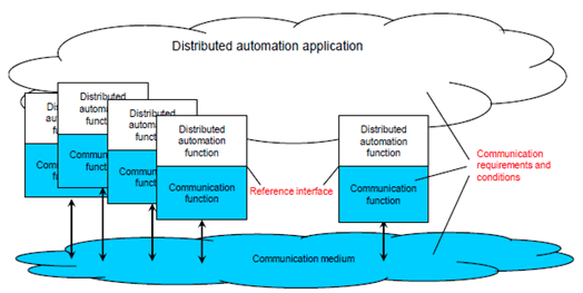
Figure 4.3.2.1.1-1: Abstract diagram of the area of consideration for industrial radio communication
(⇒ copy of original 3GPP image)
(⇒ copy of original 3GPP image)
Here, a distributed automation application system is depicted. This system includes a distributed automation application, which is the aggregation of a number of automation functions. These can be functions in sensors, measurement devices, drives, switches, I/O devices, encoders etc. Field bus systems, industrial Ethernet systems, or wireless communication systems can be used for connecting the distributed functions. The essential function of these communication systems is the distribution of messages among the distributed automation functions. Depending on the objectives, the dependability of the entire communication system and/or of its devices or its links may be of interest (more on dependability in Clause 4.3.3). Communication functions are realised by the respective hardware and software implementation.
In order for the automation application system to operate, messages need to be exchanged between spatially distributed application functions. For that process, messages are exchanged at an interface between the automation application system and the communication system. This interface is termed the reference interface. Required and guaranteed values for characteristic parameters which describe the behavioural properties of the radio communication system refer to that interface (see Clause 4.3.4.4 and [19][62]).
These characteristic parameters include dependability parameters of industrial radio communication, which are defined in [17] and [62].
The conditions that influence the behaviour of wireless communication are framed by the communication requirements of the application (e.g., length of the message), the characteristics of the communication system (e.g., output power of a transmitter), and the transmission conditions of the media (e.g., signal fluctuations caused by multipath propagation).
If a dependability assessment is to be performed, it is necessary-in accordance with the definition of the concept of dependability-to specify an asset, its function, and the conditions under which the function is to be performed. In this context, an asset is for instance a logical link (see Clause 4.3.2.1.2).
General requirements from the application point of view for the time and failure behaviour of a communication system are mostly related to an end-to-end link. It is assumed in this connection that the behaviour of the link is representative of the communication system as a whole and of the entire scope of the application.
4.3.2.1.2 Logical link p. 26
4.3.2.1.2.1 Nature and function p. 26
Starting with the general approach mentioned above, the logical link can be regarded as a possible asset within the area of consideration (see Figure 4.3.2.1.2.1-1). The conditions under which its functions are to be performed are vital for the dependability of the automation application system.
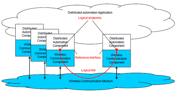
This is the link between a logical end point in a source device and the logical end point in a target device. Logical end points are elements of the reference interface, which may group several logical end points together.
The intended function of the logical link is the transmission of a sequence of messages from a logical source end point to the correct logical target end point. This is achieved by transforming each message into a form that fosters error-free transmission. The transmission process includes certain processes, e.g. repetitions, in order to fulfil the intended function. After transmission, the message is converted back into a form which is usable by the application. The message is to be available and correct at the target within a defined time. The sequence of messages at the target is to be the same as the sequence at the source.
The functional units which are necessary to fulfil this function are shown in Figure 4.3.2.1.2.1-2.
The required function can be impaired by various influences, which can lead to communication errors. Such errors are described elsewhere in the literature [17][18]. A summary of these errors is provided in Annex B. The occurrence of one of these errors influences the values of the relevant dependability parameters of the logical link.
4.3.2.1.2.2 Message transformation p. 27
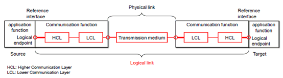
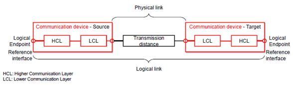
From an implementation point of view, it is hardly possible to identify communication layers and interfaces in devices in a unified manner, e.g. with reference to the Open System Interconnection (OSI) model [15]. However, the implementation of communication functions is mostly split between a higher communication layer (HCL) and a lower communication layer (LCL), which may contain different parts of the OSI reference model from implementation to implementation. Our further discussion is therefore based on a generic implementation view with HCL and LCL.
The messages to be transmitted for the intended function of a logical link are defined by strings of characters with a certain semantic. Such a character string is handed over as user data at the reference interface for transmission. If the number of characters in a message is too great for it to be transmitted as a unit, the message can be divided for transmission into several packets (fragmentation). Figure 4.3.2.1.2.2-2 uses repeated sending as a hedging method for packet loss (example of an unconfirmed service). The packets are then passed from a higher communication layer (HCL) to a lower communication layer (LCL) [Figure 4.3.2.1.2.2-1]. There, a bit stream is created and handed over to the physical layer (PL). A signal stream corresponding to the bit stream is transmitted from the physical layer of the source device to the target device. In the target device, the signal stream received is converted by physical layer into a bit stream, which is passed to the lower communication layer. There, packets are formed, handed over by the lower communication layer to the higher communication layer and grouped together into a message. Suitable mechanisms (acknowledgement, parallel transmission through different communication channels/media, multiple transmissions of identical packets, etc.) can increase the probability of the message reaching the application correctly when a packet is lost. The loss of a packet is therefore not to be equated in all cases with the loss of a message.
Figure 4.3.2.1.2.2-1 shows the transmission of a message that is broken into two packets. The transmission includes acknowledgements. If no acknowledgement is received within the required period (packet 2), the packet is transmitted again (bit stream 2). This is the main difference to, for example, Figure 4.3.2.1.2.2-2, where the packets are repeated from the beginning to protect against loss or error directly. In Figure 4.3.2.1.2.2-2, a confirmation is not sent.
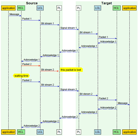
Figure 4.3.2.1.2.2-1: Illustration of message, packet and bit stream transmission for the example of repeated packet transmission
(⇒ copy of original 3GPP image)
(⇒ copy of original 3GPP image)
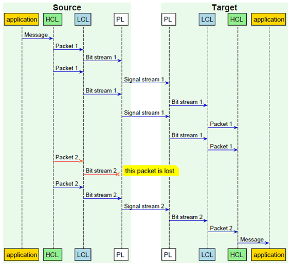
Figure 4.3.2.1.2.2-2: Illustration of message, packet and bit stream for the example of unacknowledged repeated transmission
(⇒ copy of original 3GPP image)
(⇒ copy of original 3GPP image)
4.3.2.1.3 Communication device p. 29
The communication devices-together with the physical link-determine the function and thus the dependability of the logical link (see Figure 4.3.2.1.3-1). The function of the communication devices is the correct sending and correct receipt of sequences of messages. The methods and algorithms implemented in the communication devices should take the best possible account of the transmission conditions during message transmission, and fulfil the requirements for message transmission as well as possible.
Apart from the methods and algorithms themselves, their implementation in hardware and software is also of importance. The errors listed in Annex C can have an impact on dependability.
4.3.2.1.4 Communication system p. 30
The communication system as an asset represents a quantity of logical links whose message transmissions are implemented by a number of wireless devices via one or more media. The communication system function to be provided consists in transmitting messages for all the logical links in the distributed application. This function is to be performed for a defined period, the operating time of the automation application.
In an automation application system it is paramount that requirements pertaining to logical links are fulfilled. These requirements and the conditions can be very different from one case and implementation to the other. The functions (services and protocols) for individual logical links can therefore also be different. In spite of these differences, some of the logical links share communication devices and media. Consequently, the communication system as a whole is an asset for dependability assessment in the examination of system and application aspects.
![]()
![]()
![]()