Content for TR 38.835 Word version: 18.0.1
1…
4…
5…
6
A
B…
B.1.2
B.1.3
B.1.4
B.1.5
B.1.6
B.1.7
B.1.8
B.1.9
B.1.10
B.2…
B.2.2
B.2.3
B.2.4
B.2.5
B.2.6
B.2.7
B.2.8
B.2.9
B.2.10
B.2.11
B.2.12
B.2.13
B.2.14
B.2.15
B.2.16
B.2.17
B.2.18
C…
5 XR Enhancements for NR
5.1 XR Awareness
5.1.1 General
5.1.2 Layer 2 Structure
5.2 Power Saving Techniques
5.2.1 Physical Layer Enhancements
5.2.2 Layer 2 Enhancements
5.3 Capacity Improvements Techniques
5.3.1 Physical Layer Enhancements
5.3.2 Layer 2 Enhancements
...
...
5 XR Enhancements for NR p. 13
5.1 XR Awareness p. 13
5.1.1 General p. 13
In both uplink and downlink, XR-Awareness contributes to optimizations of gNB radio resource scheduling and relies at least on the notions of PDU Set and Data Burst (see TR 23.700-60): a PDU Set is composed of one or more PDUs carrying the payload of one unit of information generated at the application level (e.g. a frame or video slice), while a Data Burst is a set of data PDUs generated and sent by the application in a short period of time.
The following information may be provided by the CN to RAN (see TR 23.700-60):
-
Semi-static information per QoS flow:
- Periodicity for UL and DL traffic of the QoS Flow provided via TSCAI/TSCAC;
- DL Traffic jitter information (e.g. jitter range) associated with each periodicity of the QoS flow provided via TSCAI/TSCAC.
-
PDU Set QoS parameters of the QoS flow (i.e. applicable to all PDU sets of the QoS flow) provided by the SMF via NGAP:
- PDU Set Error Rate (PSER): defines an upper bound for a rate of non-congestion related PDU Set losses between RAN and the UE (see TR 23.700-60).
- PDU Set Delay Budget (PSDB): time between reception of the first PDU (at the UPF in DL, at the UE in UL) and the successful delivery of the last arrived PDU of a PDU Set (at the UE in DL, at the UPF in UL). PSDB is an optional parameter and when provided, the PSDB supersedes the PDB (see TR 23.700-60).
- PDU Set Integrated Handling Indication (PSIHI): indicates whether all PDUs of the PDU Set are needed for the usage of PDU Set by application layer.
-
PDU Set Information and Identification (dynamic information for DL provided by user plane in GTP-U header):
- PDU Set Sequence Number;
- PDU Set Size in bytes (FFS);
- PDU SN within a PDU Set;
- Indication of End PDU of the PDU Set;
- PDU Set Importance (PSI): identifies the relative importance of a PDU Set compared to other PDU Sets within a QoS Flow. RAN may use it for PDU Set level packet discarding in presence of congestion;
- End of Data Burst indication in the header of the last PDU of the Data Burst (optional).
5.1.2 Layer 2 Structure p. 14
Depending on how the mapping of PDU Sets onto QoS flows is done in the NAS and how QoS flows are mapped onto DRBs in the AS, we can distinguish the following alternatives (as depicted on Figure 5.1.2-1 below):
- 111: one-to-one mapping between types of PDU Sets and QoS flows in the NAS and one-to-one mapping between QoS flows and DRBs in the AS. From a Layer 2 structure viewpoint, this alternative is already possible and requires as many DRBs as types of PDU Sets. Providing different QoS for the types of PDU Sets sent in different DRBs is already possible.
- NN1: one-to-one mapping between types of PDU Sets and QoS flows in the NAS and possible multiplexing of QoS flows in one DRB in the AS. From a Layer 2 structure viewpoint, this alternative is already possible but gives each QoS flows multiplexed in a DRB the same QoS. Providing different QoS for the types of PDU Sets (i.e. QoS flows) multiplexed in a single DRB is currently not possible.
- N11: possible multiplexing of types of PDU Sets in one QoS flow in the NAS and one-to-one mapping between QoS flows and DRBs in the AS. From a Layer 2 structure viewpoint, this alternative is already possible but gives each QoS flow/DRB one QoS. Providing different QoS for the types of PDU Sets multiplexed in a single QoS flow/DRB is currently not possible.
- N1N: possible multiplexing of types of PDU Sets in one QoS flow in the NAS and demultiplexing of types of PDU Sets from one QoS flow on multiple DRBs in the AS. From a Layer 2 structure viewpoint, demultiplexing of types of PDU Sets from one QoS flow onto multiple DRBs is currently not possible.
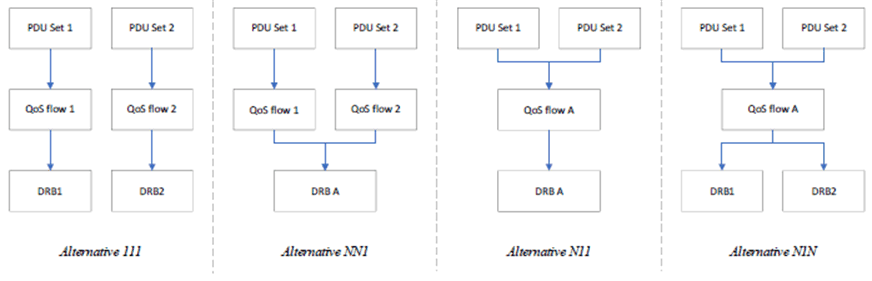
When comparing these alternatives, it was agreed that a QoS flow cannot be mapped onto multiple DRBs in the uplink, thereby excluding alternative N1N. For the other alternatives, providing different QoS by splitting PDU sets of one DRB to different RLC bearers will not be possible i.e. that splitting a DRB onto multiple RLC entities will remain limited to existing cases (e.g. duplication).
In addition, the notion of PDU Set does not impact the granularity of:
- SDAP SDU handling: SDAP still maps every incoming SDU to a single PDU for a single PDCP entity;
- Retransmissions: HARQ still relies on MAC PDUs and ARQ on RLC PDUs.
5.2 Power Saving Techniques p. 15
5.2.1 Physical Layer Enhancements p. 15
The evaluation results for proposed and studied power saving enhancement schemes are available in Annex B.2.
5.2.2 Layer 2 Enhancements p. 15
Most XR frame rates (15, 30, 45, 60, 72, 90 and 120fps) correspond to periodicities which are not an integer (66.66, 33.33, 22.22, 16.66, 13.88, 11.11 and 8.33ms respectively). The corresponding support by DRX will be dealt with in a semi-static manner at least (e.g. via RRC signalling).
In addition, RRC pre-configuration and switching of configurations of DRX can be considered for enhancements of XR power saving.
5.3 Capacity Improvements Techniques p. 15
5.3.1 Physical Layer Enhancements p. 15
The following enhancements for configured grant-based transmission are recommended:
- Multiple CG PUSCH transmission occasions in a period of a single CG PUSCH configuration;
- Dynamic indication of unused CG PUSCH occasion(s) based on UCI (e.g., CG-UCI or a new UCI) by the UE.
5.3.2 Layer 2 Enhancements p. 15
In order to enhance the scheduling of uplink resources for XR, the following improvements are envisioned:
- One or more additional BS table(s) to reduce the quantisation errors in BSR reporting (e.g. for high bit rates);
- Delay knowledge of buffered data, consisting of e.g. remaining time, and distinguishing how much data is buffered for which delay. It is to be determined whether the delay information is reported as part of BSR or as a new MAC CE. Also, how the delay information can be up to date considering e.g. scheduling and transmission delays needs to be investigated further.
- Additional BSR triggering conditions to allow timely availability of buffer status information can be investigated further.
- Delivery of some assistance information (e.g. periodicity) reusing TSCAI as a baseline. Whether additional mechanism is required can be further considered with an assumption that all information may not be always available at UE application.
- Signalling of UL traffic arrival information from the UE to the gNB e.g. to cope with jitter in case of tethering (FFS).
![]()
![]()
![]()