Content for TS 38.321 Word version: 18.0.0
1…
4…
5…
5.1.2…
5.2…
5.4…
5.4.4…
5.5…
5.9…
5.18…
5.18.18…
5.19…
5.22…
5.22.1.4…
5.22.2…
5.23…
6…
6.1.3…
6.1.3.8…
6.1.3.11…
6.1.3.17…
6.1.3.21…
6.1.3.26…
6.1.3.31…
6.1.3.37…
6.1.3.42…
6.1.3.49…
6.1.3.53…
6.1.3.59…
6.1.3.64…
6.1.3.70…
6.1.3.74…
6.1.3.79…
6.1.4…
6.2…
7…
6.1.3.53 Inter-UE Coordination Information MAC CE
6.1.3.54 Inter-UE Coordination Request MAC CE
6.1.3.55 Enhanced SCell Activation/Deactivation MAC CEs
6.1.3.56 Timing Advance Report MAC CE
6.1.3.57 Differential Koffset MAC CE
6.1.3.58 BFD-RS Indication MAC CE
...
...
6.1.3.53 Inter-UE Coordination Information MAC CE |R17| p. 256
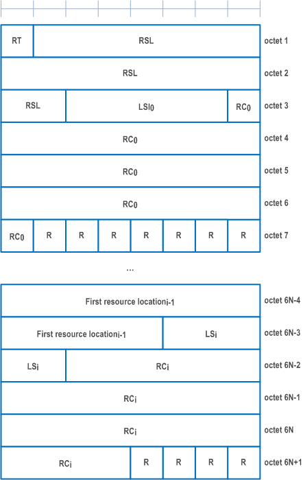
The Inter-UE Coordination Information MAC CE is identified by a MAC subheader with LCID as specified in Table 6.2.4-1. The priority of the Inter-UE Coordination Information MAC CE is fixed to '1' for Logical Channel Prioritization (LCP) procedure. It has a variable size with following fields:
- RT: This field indicates the resource set type, i.e., preferred resource set or non-preferred resource set, as the codepoint value of the SCI format 2-C resourceSetType field as specified in TS 38.212.
- RSL: This field indicates the location of reference slot, as the codepoint value of the SCI format 2-C referenceSlotLocation field as specified in TS 38.212. The length of the field is 17 bits. If the length of referenceSlotLocation field in SCI format 2-C as specified in TS 38.212 is shorter than 17 bit, this field contains referenceSlotLocation field using the LSB bits;
- LSIi: This field indicates lowest subchannel indices for the first resource location of each TRIV, as the codepoint value of the SCI format 2-C lowestIndices field as specified in TS 38.212. LSI0 indicates lowest subchannel indices for the first resource location of TRIV within the first resource combination, LSI1 indicates lowest subchannel indices for the first resource location of TRIV within the second resource combination and so on. The length of the field is 5 bits. If the length of lowestIndices field in SCI format 2-C as specified in TS 38.212 is shorter than 5 bit, this field contains lowestIndices field using the LSB bits;
- RCi: This field indicates resource combination, as the codepoint value of the SCI format 2-C resourceCombination field as specified in TS 38.212. The number of RC is based on upper bound of the L field in the MAC subheader as indicated in clause 6.2.1. RC0 indicates the first resource combination, RC1 indicates the second resource combination and so on. The length of the field is 26 bits. If the length of resourceCombination field in SCI format 2-C as specified in TS 38.212 is shorter than 26 bit, this field contains resourceCombination field using the LSB bits;
- First resource locationi-1: This field indicates first resource location, as the codepoint value of the SCI format 2-C firstResourceLocation field as specified in TS 38.212. First Resource Location0 indicates the first resource location for the second resource combination, First Resource Location1 indicates the first resource location for the third resource combination and so on. The length of the field is 13 bits. If the length of firstResourceLocation field in SCI format 2-C as specified in TS 38.212 is shorter than 13 bit, this field contains firstResourceLocation field using the LSB bits;
- R: Reserved bit, set to 0.
6.1.3.54 Inter-UE Coordination Request MAC CE |R17| p. 257
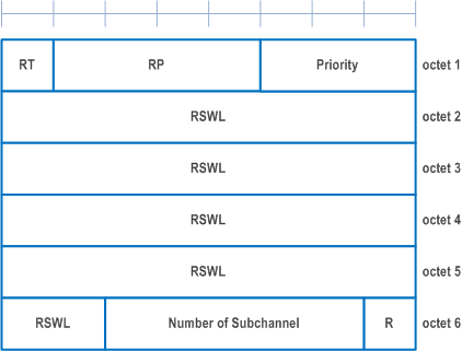
The Inter-UE Coordination request MAC CE is identified by a MAC subheader with LCID as specified in Table 6.2.4-1. The priority of the Inter-UE Coordination Request MAC CE is fixed to '1' for Logical Channel Prioritization (LCP) procedure. It has a fixed size of 48 bits with following fields:
- RT: If the value of sl-DetermineResourceType (as specified in clause 6.3.5 of TS 38.331) is set to ueb, this field indicates the resource set type, i.e., preferred resource set or non-preferred resource set, as the codepoint value of the SCI format 2-C resourceSetType field as specified in TS 38.212. This field is ignored if the value of sl-DetermineResourceType is set to uea;
- RP: This field indicates the resource reservation period, as the codepoint value of the SCI format 2-C resourceReservationPeriod field as specified in TS 38.212. The length of the field is 4 bits. If the length of resourceReservationPeriod field in SCI format 2-C as specified in TS 38.212 is shorter than 4 bit, this field contains resourceReservationPeriod field using the LSB bits;
- Priority: This field indicates the priority, as the codepoint value of the SCI format 2-C priority field as specified in TS 38.212. The length of the field is 3 bits;
- RSWL: This field indicates resource selection window location, as the codepoint value of the SCI format 2-C resourceSelectionWindowLocation field as specified in TS 38.212. The length of the field is 34 bits. If the length of resourceSelectionWindowLocation field in SCI format 2-C as specified in TS 38.212 is shorter than 34 bit, this field contains resourceSelectionWindowLocation field using the LSB bits;
- Number of Subchannel: This field indicates the number of subchannels, as the codepoint value of the SCI format 2-C numberOfSubchannel field as specified in TS 38.212. The length of the field is 5 bits. If the length of numberOfSubchannel field in SCI format 2-C as specified in TS 38.212 is shorter than 5 bit, this field contains numberOfSubchannel field using the LSB bits;
- R: Reserved bit, set to 0.
6.1.3.55 Enhanced SCell Activation/Deactivation MAC CEs |R17| p. 258
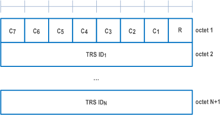
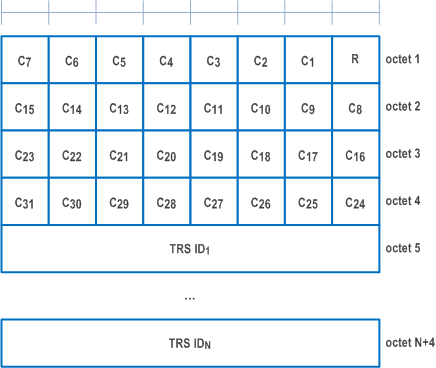
The Enhanced SCell Activation/Deactivation MAC CE with one octet Ci field is identified by a MAC subheader with eLCID as specified in Table 6.2.1-1b. It has a variable size and consists of seven C-fields, one R-field and zero or more TRS IDj fields in ascending order based on the ScellIndex for SCells indicated by the Ci field(s) to be activated. The Enhanced SCell Activation/Deactivation MAC CE of with one octet Ci field is defined as follows (Figure 6.1.3.55-1).
The Enhanced SCell Activation/Deactivation MAC CE with four octet Ci field is identified by a MAC subheader with eLCID as specified in Table 6.2.1-1b. It has a variable size and consists of 31 C-fields, one R-field and zero or more TRS IDj fields in ascending order based on the ScellIndex for SCells indicated by the Ci field(s) to be activated. The Enhanced SCell Activation/Deactivation MAC CE with four octet Ci field is defined as follows (Figure 6.1.3.55-2).
- Ci: If there is an SCell configured for the MAC entity with SCellIndex i as specified in TS 38.331, this field indicates the activation/deactivation status of the SCell with SCellIndex i, else the MAC entity shall ignore the Ci field. The Ci field is set to 1 to indicate that the SCell with SCellIndex i shall be activated and that a TRS IDj field is included for the SCell. The Ci field is set to 0 to indicate that the SCell with SCellIndex i shall be deactivated and that no TRS ID field is included for this SCell;
- TRS IDj: If TRS IDj is set to a non-zero value, it indicates the corresponding TRS address by scellActivationRS-Id as specified in TS 38.331 is activated. If TRS IDj is set to zero, it indicates that no TRS is used for the corresponding SCell;
- R: Reserved bit, set to 0.
6.1.3.56 Timing Advance Report MAC CE |R17| p. 259
The Timing Advance Report MAC CE is identified by MAC subheader with LCID as specified in Table 6.2.1-2. It has a fixed size and consists of two octets defined as follows (Figure 6.1.3.56-1):
- R: Reserved bit, set to 0;
- Timing Advance: In FR1 except for ATG, the Timing Advance field indicates the least integer number of slots for NTN or symbols for ATG, using subcarrier spacing of 15 kHz for NTN and either 15 kHz or 30 kHz for ATG, greater than or equal to the Timing Advance value (see clause 4.3.1 of TS 38.211). For ATG, the Timing Advance field indicates the least integer number of symbols greater than or equal to the Timing Advance value (see clause 4.3.1 of TS 38.211). The symbol duration is based on the subcarriers spacing the UE is currently configured with. In this release of the specification, only 15 kHz and 30 kHz SCS are applicable and only values 1 … 56 are used. The length of the field is 14 bits.

6.1.3.57 Differential Koffset MAC CE |R17| p. 260
The Differential Koffset MAC CE is identified by a MAC subheader with eLCID as specified in Table 6.2.1-1b. It has a fixed size and consists of a single octet defined as follows (Figure 6.1.3.57-1):
- R: Reserved bit, set to 0;
- Differential Koffset: This field indicates the differential Koffset in the number of slots (see clause 4.2 of TS 38.213), using subcarrier spacing of 15 kHz. The length of the field is 6 bits.

6.1.3.58 BFD-RS Indication MAC CE |R17| p. 260
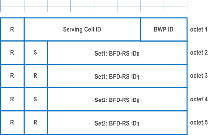
The BFD-RS Indication MAC CE is identified by a MAC subheader with eLCID as specified in Table 6.2.1-1b. It has a variable size, and includes a BFD-RS-ID0 field and a BFD-RS-ID1 field (optional) of failureDetectionSet1, and a BFD-RS-ID0 field and a BFD-RS-ID1 field (optional) of failureDetectionSet2.
It has a variable size consisting of following fields:
- Serving Cell ID: This field indicates the identity of the Serving Cell for which the MAC CE applies. The length of the field is 5 bits;
- BWP ID: This field indicates a DL BWP for which the MAC CE applies as the codepoint of the DCI bandwidth part indicator field as specified in TS 38.213. The length of the BWP ID field is 2 bits;
- S: This field indicates the presence of the octet containing the BFD-RS ID1 of the same BFD-RS set. The S field set to 1 indicates that the octet containing BFD-RS ID1 is included. The S field set to 0 indicates that the octet containing the BFD-RS ID1 of the same BFD-RS set is not included;
- BFD-RS IDi: This field indicates the BFD-RS resource from failureDetectionSet1 or failureDetectionSet2 as specified in TS 38.331;
- R: Reserved bit, set to 0.
