Content for TS 38.321 Word version: 18.1.0
1…
4…
5…
5.1.2…
5.2…
5.4…
5.4.4…
5.5…
5.9…
5.18…
5.18.18…
5.19…
5.22…
5.22.1.4…
5.22.2…
5.23…
6…
6.1.3…
6.1.3.8…
6.1.3.11…
6.1.3.17…
6.1.3.21…
6.1.3.26…
6.1.3.31…
6.1.3.37…
6.1.3.42…
6.1.3.49…
6.1.3.53…
6.1.3.59…
6.1.3.64…
6.1.3.70…
6.1.3.74…
6.1.3.79…
6.1.4…
6.2…
7…
4 General
4.1 Introduction
4.2 MAC architecture
4.2.1 General
4.2.2 MAC Entities
4.3 Services
4.3.1 Services provided to upper layers
4.3.2 Services expected from physical layer
4.4 Functions
4.5 Channel structure
4.5.1 General
4.5.2 Transport Channels
4.5.3 Logical Channels
4.5.4 Mapping of Transport Channels to Logical Channels
4.5.4.1 General
4.5.4.2 Uplink mapping
4.5.4.3 Downlink mapping
4.5.4.4 Sidelink mapping
...
...
4 General p. 14
4.1 Introduction p. 14
The objective of this clause is to describe the MAC architecture and the MAC entity of the UE from a functional point of view.
4.2 MAC architecture p. 14
4.2.1 General p. 14
This clause describes a model of the MAC i.e. it does not specify or restrict implementations.
RRC is in control of the MAC configuration.
4.2.2 MAC Entities p. 14
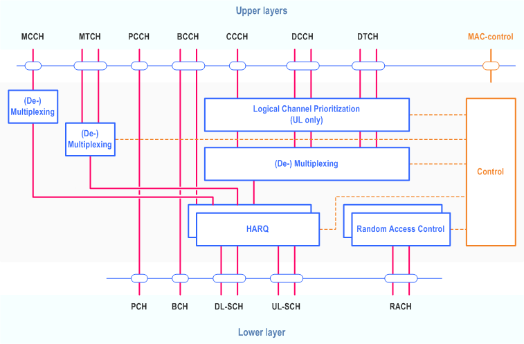
The MAC entity of the UE handles the following transport channels:
- Broadcast Channel (BCH);
- Downlink Shared Channel(s) (DL-SCH);
- Paging Channel (PCH);
- Uplink Shared Channel(s) (UL-SCH);
- Random Access Channel(s) (RACH).

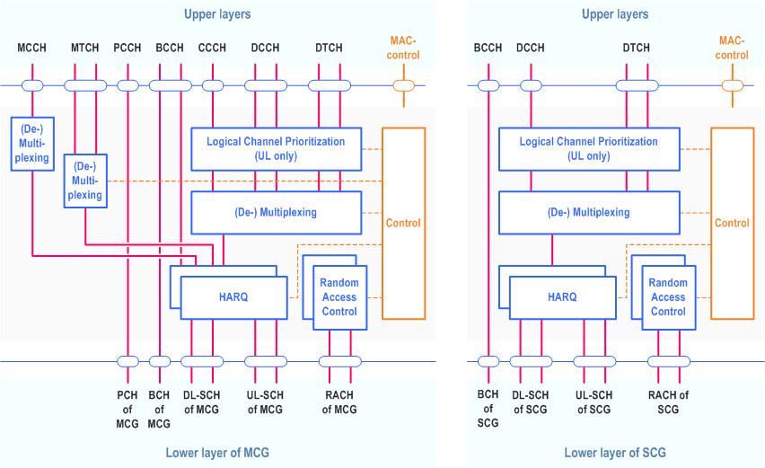
Figure 4.2.2-2 illustrates one possible structure for the MAC entities when MCG and SCG are configured.

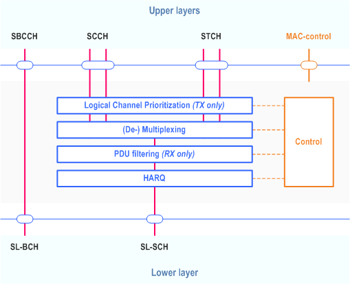
In addition, the MAC entity of the UE handles the following transport channel for sidelink:
- Sidelink Shared Channel (SL-SCH);
- Sidelink Broadcast Channel (SL-BCH).

4.3 Services p. 16
4.3.1 Services provided to upper layers p. 16
The MAC sublayer provides the following services to upper layers:
- data transfer;
- radio resource allocation.
4.3.2 Services expected from physical layer p. 16
The MAC sublayer expects the following services from the physical layer:
- data transfer services;
- signalling of HARQ feedback;
- signalling of Scheduling Request;
- measurements (e.g. Channel Quality Indication (CQI)).
4.4 Functions p. 16
The MAC sublayer supports the following functions:
- mapping between logical channels and transport channels;
- multiplexing of MAC SDUs from one or different logical channels onto transport blocks (TB) to be delivered to the physical layer on transport channels;
- demultiplexing of MAC SDUs to one or different logical channels from transport blocks (TB) delivered from the physical layer on transport channels;
- scheduling information reporting;
- error correction through HARQ;
- logical channel prioritization;
- priority handling between overlapping resources of one UE;
- radio resource selection.
| MAC function | Downlink | Uplink | Sidelink TX | Sidelink RX |
|---|---|---|---|---|
| Mapping between logical channels and transport channels | X | X | X | X |
| Multiplexing | X | X | ||
| Demultiplexing | X | X | ||
| Scheduling information reporting | X | X | ||
| Error correction through HARQ | X | X | X | X |
| Logical Channel prioritization | X | X | ||
| Radio resource selection | X |
4.5 Channel structure p. 17
4.5.1 General p. 17
The MAC sublayer operates on the channels defined below; transport channels are SAPs between MAC and Layer 1, logical channels are SAPs between MAC and RLC.
4.5.2 Transport Channels p. 17
The MAC sublayer uses the transport channels listed in Table 4.5.2-1 below.
| Transport channel name | Acronym | Downlink | Uplink | Sidelink |
|---|---|---|---|---|
| Broadcast Channel | BCH | X | ||
| Downlink Shared Channel | DL-SCH | X | ||
| Paging Channel | PCH | X | ||
| Uplink Shared Channel | UL-SCH | X | ||
| Random Access Channel | RACH | X | ||
| Sidelink Broadcast Channel | SL-BCH | X | ||
| Sidelink Shared Channel | SL-SCH | X |
4.5.3 Logical Channels p. 17
The MAC sublayer provides data transfer services on logical channels. To accommodate different kinds of data transfer services, multiple types of logical channels are defined i.e. each supporting transfer of a particular type of information.
Each logical channel type is defined by what type of information is transferred.
The MAC sublayer provides the control and traffic channels listed in Table 4.5.3-1 below.
| Logical channel name | Acronym | Control channel | Traffic channel |
|---|---|---|---|
| Broadcast Control Channel | BCCH | X | |
| Paging Control Channel | PCCH | X | |
| Common Control Channel | CCCH | X | |
| Dedicated Control Channel | DCCH | X | |
| Dedicated Traffic Channel | DTCH | X | |
| MBS Control Channel | MCCH | X | |
| MBS Traffic Channel | MTCH | X | |
| Sidelink Broadcast Control Channel | SBCCH | X | |
| Sidelink Control Channel | SCCH | X | |
| Sidelink Traffic Channel | STCH | X |
4.5.4 Mapping of Transport Channels to Logical Channels p. 18
4.5.4.1 General p. 18
The MAC entity is responsible for mapping logical channels onto transport channels. This mapping depends on the multiplexing that is configured by RRC.
4.5.4.2 Uplink mapping p. 18
The uplink logical channels can be mapped as described in Table 4.5.4.2-1.
|
Transport channel
Logical channel
|
UL-SCH | RACH |
|---|---|---|
| CCCH | X | |
| DCCH | X | |
| DTCH | X |
4.5.4.3 Downlink mapping p. 18
The downlink logical channels can be mapped as described in Table 4.5.4.3-1.
|
Transport channel
Logical channel
|
BCH | PCH | DL-SCH |
|---|---|---|---|
| BCCH | X | X | |
| PCCH | X | ||
| CCCH | X | ||
| DCCH | X | ||
| DTCH | X | ||
| MCCH | X | ||
| MTCH | X |
4.5.4.4 Sidelink mapping |R16| p. 18
The sidelink logical channels can be mapped as described in Table 4.5.4.4-1.
|
Transport channel
Logical channel
|
SL-BCH | SL-SCH |
|---|---|---|
| SBCCH | X | |
| SCCH | X | |
| STCH | X |