Content for TS 38.104 Word version: 18.3.0
5.3A BS channel bandwidth for CA
5.3A.1 Transmission bandwidth configuration for CA
5.3A.2 Minimum guardband and transmission bandwidth configuration for CA
...
...
5.3A BS channel bandwidth for CA p. 45
5.3A.1 Transmission bandwidth configuration for CA p. 45
For carrier aggregation, the transmission bandwidth configuration is defined per component carrier and the requirement is specified in clause 5.3.2.
5.3A.2 Minimum guardband and transmission bandwidth configuration for CA p. 45
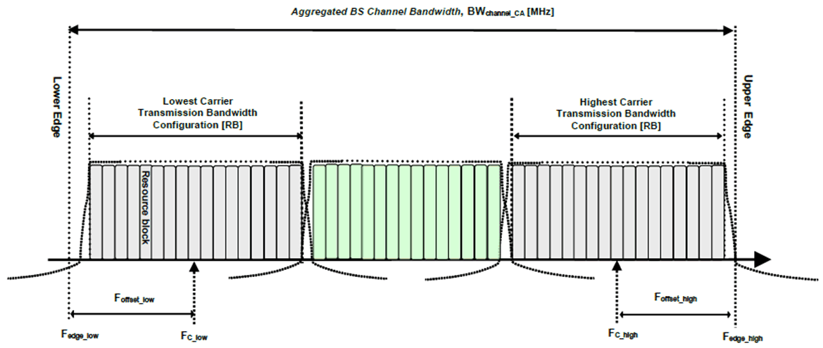
For intra-band contiguous carrier aggregation, Aggregated BS Channel Bandwidth and Guard Bands are defined as follows, see Figure 5.3A.2-1.

Figure 5.3A.2-1: Definition of Aggregated BS Channel Bandwidth for intra-band carrier aggregation
(⇒ copy of original 3GPP image)
(⇒ copy of original 3GPP image)
The aggregated BS Channel Bandwidth, BWChannel_CA, is defined as
BWChannel_CA = Fedge,high – Fedge,low (MHz)
The lower bandwidth edge Fedge,low and the upper bandwidth edge Fedge,high of the aggregated BS channel bandwidth are used as frequency reference points for transmitter and receiver requirements and are defined by
Fedge,low = FC,low – Foffset,low
Fedge,high = FC,high + Foffset,high
The lower and upper frequency offsets depend on the transmission bandwidth configurations of the lowest and highest assigned edge component carrier and are defined as
Foffset,low = (NRB,low*12 + 1)*SCSlow/2 + BWGB,low (MHz)
Foffset,high = (NRB,high*12 – 1)*SCShigh/2 + BWGB,high (MHz)
NRB,low and NRB,high are the transmission bandwidth configurations according to Table 5.3.2-1 or Table 5.3.2-2 or Table 5.3.2-3 for the lowest and highest assigned component carrier, SCSlow and SCShigh are the sub-carrier spacing for the lowest and highest assigned component carrier respectively. SCSlow, SCShigh, NRB,low, NRB,high, BWGB,low and BWGB,high use the largest μ value among the subcarrier spacing configurations supported in the operating band for both of the channel bandwidths according to Table 5.3.5-1 and BWGB,low and BWGB,high are the minimum guard band for lowest and highest assigned component carrier according to Table 5.3.3-1 for the said μ value. In case there is no common μ value for both of the channel bandwidths, μ=1 is used for SCSlow, SCShigh, NRB,low, NRB,high, BWGB,low and BWGB,high.
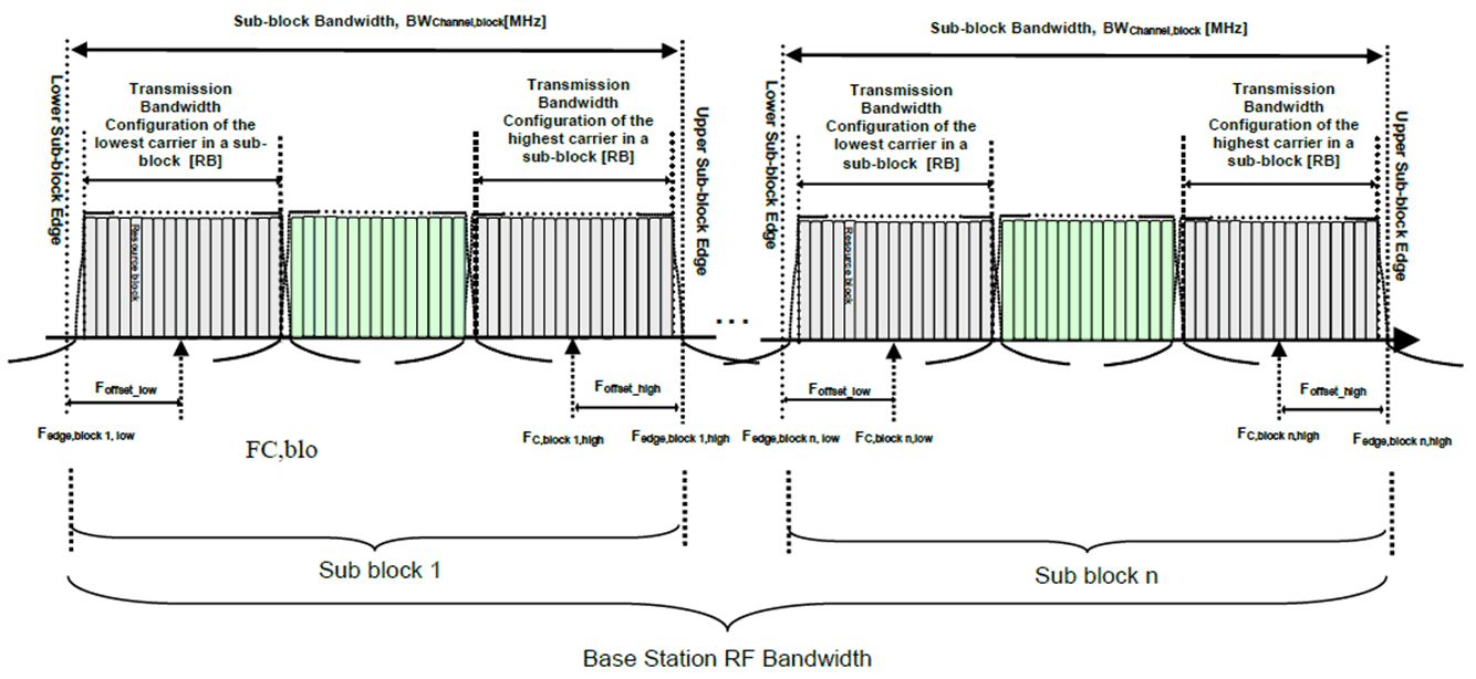
For intra-band non-contiguous carrier aggregation sub-block bandwidth and sub-block edges are defined as follows, see Figure 5.3A.2-2.

Figure 5.3A.2-2: Definition of sub-block bandwidth for intra-band non-contiguous spectrum
(⇒ copy of original 3GPP image)
(⇒ copy of original 3GPP image)
The lower sub-block edge of the sub-block bandwidth (BWChannel,block) is defined as follows:
Fedge,block,low = FC,block,low – Foffset,low
The upper sub-block edge of the sub-block bandwidth is defined as follows:
Fedge,block,high = FC,block,high + Foffset,high
The sub-block bandwidth, BWChannel,block, is defined as follows:
BWChannel,block = Fedge,block,high – Fedge,block,low (MHz)
The lower and upper frequency offsets Foffset,block,low and Foffset,block,high depend on the transmission bandwidth configurations of the lowest and highest assigned edge component carriers within a sub-block and are defined as
Foffset,block,low = (NRB,low*12 + 1)*SCSlow/2 + BWGB,low (MHz)
Foffset,block,high = (NRB,high*12 – 1)*SCShigh/2 + BWGB,high (MHz)
where NRB,low and NRB,high are the transmission bandwidth configurations according to Table 5.3.2-1 or Table 5.3.2-2 for the lowest and highest assigned component carrier within a sub-block, respectively. SCSlow and SCShigh are the sub-carrier spacing for the lowest and highest assigned component carrier within a sub-block, respectively. SCSlow, SCShigh, NRB,low, NRB,high, BWGB,low and BWGB,high use the largest μ value among the subcarrier spacing configurations supported in the operating band for both of the channel bandwidths according to Table 5.3.5-1 and BWGB,low and BWGB,high are the minimum guard band for lowest and highest assigned component carrier according to Table 5.3.3-1 for the said μ value. In case there is no common μ value for both of the channel bandwidths, μ=1 is used for SCSlow, SCShigh, NRB,low, NRB,high, BWGB,low and BWGB,high.
The sub-block gap size between two consecutive sub-blocks Wgap is defined as follows:
Wgap = Fedge,block n+1,low – Fedge,block n,high (MHz)