Content for TS 33.401 Word version: 17.3.0
1…
4
5…
6…
6.2…
7…
7.2.5…
7.2.8
7.2.9…
7.3…
8…
9…
10…
11…
15…
A…
B…
C…
C.1.6
C.2…
C.2.7
C.2.8
C.3…
C.4.7
D…
E…
E.2…
E.3…
F…
G…
H…
I…
K…
B Algorithms for ciphering and integrity protection
B.0 Null ciphering and integrity protection algorithms
B.1 128-bit ciphering algorithm
B.2 128-Bit integrity algorithm
...
...
B (Normative) Algorithms for ciphering and integrity protection p. 89
B.0 Null ciphering and integrity protection algorithms p. 89
The EEA0 algorithm shall be implemented such that it has the same effect as if it generates a KEYSTREAM of all zeroes (see clause B.1.1). The length of the KEYSTREAM generated shall be equal to the LENGTH input parameter. The generated KEYSTREAM requires no other input parameters but the LENGTH. Apart from this, all processing performed in association with ciphering shall be exactly the same as with any of the ciphering algorithms specified in this Annex.
The EIA0 algorithm shall be implemented in such way that it shall generate a 32 bit MAC-I/NAS-MAC and XMAC-I/XNAS-MAC of all zeroes (see clause B.2.1). Replay protection shall not be activated when EIA0 is activated. All processing performed in association with integrity (except for replay protection) shall be exactly the same as with any of the integrity algorithms specified in this Annex except that the receiver does not check the received MAC.
EIA0 shall be used only for emergency calling for unauthenticated UEs in LSM.
B.1 128-bit ciphering algorithm p. 89
B.1.1 Inputs and outputs p. 89
The input parameters to the ciphering algorithm are a 128-bit cipher key named KEY, a 32-bit COUNT, a 5-bit bearer identity BEARER, the 1-bit direction of the transmission i.e. DIRECTION, and the length of the keystream required i.e. LENGTH. The DIRECTION bit shall be 0 for uplink and 1 for downlink.
Figure B.1-1 illustrates the use of the ciphering algorithm EEA to encrypt plaintext by applying a keystream using a bit per bit binary addition of the plaintext and the keystream. The plaintext may be recovered by generating the same keystream using the same input parameters and applying a bit per bit binary addition with the ciphertext.
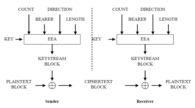
Based on the input parameters the algorithm generates the output keystream block KEYSTREAM which is used to encrypt the input plaintext block PLAINTEXT to produce the output ciphertext block CIPHERTEXT.
The input parameter LENGTH shall affect only the length of the KEYSTREAM BLOCK, not the actual bits in it.
B.1.2 128-EEA1 p. 90
128-EEA1 is based on SNOW 3G and is identical to UEA2 as specified in TS 35.215. The used IV is constructed the same way as in clause 3.4 of that TS.
B.1.3 128-EEA2 p. 90
128-EEA2 is based on 128-bit AES [15] in CTR mode [16].
The sequence of 128-bit counter blocks needed for CTR mode T1, T2, …, Ti, … shall be constructed as follows:
The most significant 64 bits of T1 consist of COUNT[0] .. COUNT[31] │ BEARER[0] .. BEARER[4] │ DIRECTION │ 026 (i.e. 26 zero bits). These are written from most significant on the left to least significant on the right, so for example COUNT[0] is the most significant bit of T1.
The least significant 64 bits of T1 are all 0.
Subsequent counter blocks are then obtained by applying the standard integer incrementing function (according to Appendix B1 in [16]) mod 264 to the least significant 64 bits of the previous counter block.
B.1.4 128-EEA3 |R11| p. 90
128-EEA3 is based on ZUC and specified in TS 35.221.
B.2 128-Bit integrity algorithm p. 91
B.2.1 Inputs and outputs p. 91
The input parameters to the integrity algorithm are a 128-bit integrity key named KEY, a 32-bit COUNT, a 5-bit bearer identity called BEARER, the 1-bit direction of the transmission i.e. DIRECTION, and the message itself i.e MESSAGE. The DIRECTION bit shall be 0 for uplink and 1 for downlink. The bit length of the MESSAGE is LENGTH.
Figure B.2-1 illustrates the use of the integrity algorithm EIA to authenticate the integrity of messages.
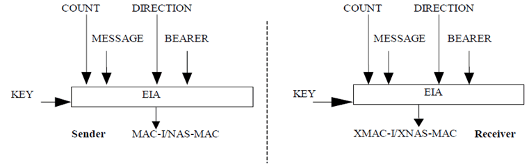
Based on these input parameters the sender computes a 32-bit message authentication code (MAC-I/NAS-MAC) using the integrity algorithm EIA. The message authentication code is then appended to the message when sent. For integrity protection algorithms other than EIA0 the receiver computes the expected message authentication code (XMAC-I/XNAS-MAC) on the message received in the same way as the sender computed its message authentication code on the message sent and verifies the data integrity of the message by comparing it to the received message authentication code, i.e. MAC-I/NAS-MAC.
B.2.2 128-EIA1 p. 91
128-EIA1 is based on SNOW 3G and is implemented in the same way as UIA2 as specified in TS 35.215. The used IV is constructed the same way as in subclause 4.4 of that TS, with the only difference being that FRESH [0], … FRESH [31] shall be replaced by BEARER[0] … BEARER[4] │ 027 (i.e. 27 zero bits)
B.2.3 128-EIA2 p. 91
128-EIA2 is based on 128-bit AES [15] in CMAC mode [17].
The bit length of MESSAGE is BLENGTH.
The input to CMAC mode is a bit string M of length Mlen (see [17], section 5.5). M is constructed as follows:
M0 .. M31 = COUNT[0] .. COUNT[31]
M32 .. M36 = BEARER[0] .. BEARER[4]
M37 = DIRECTION
M38 .. M63 = 026 (i.e. 26 zero bits)
M64 .. MBLENGTH+63 = MESSAGE[0] .. MESSAGE[BLENGTH-1]
and so Mlen = BLENGTH + 64.
AES in CMAC mode is used with these inputs to produce a Message Authentication Code T (MACT) of length Tlen = 32. T is used directly as the 128-EIA2 output MACT[0] .. MACT[31], with MACT[0] being the most significant bit of T.
B.2.4 128-EIA3 |R11| p. 92
128-EIA3 is based on ZUC and specified in TS 35.221.
![]()
![]()
![]()