ETSI (SCP) TS 102 221
Smart Cards – UICC-Terminal Interface –
Physical and Logical Characteristics
V18.2.0 (PDF)
2024/06 205 p.
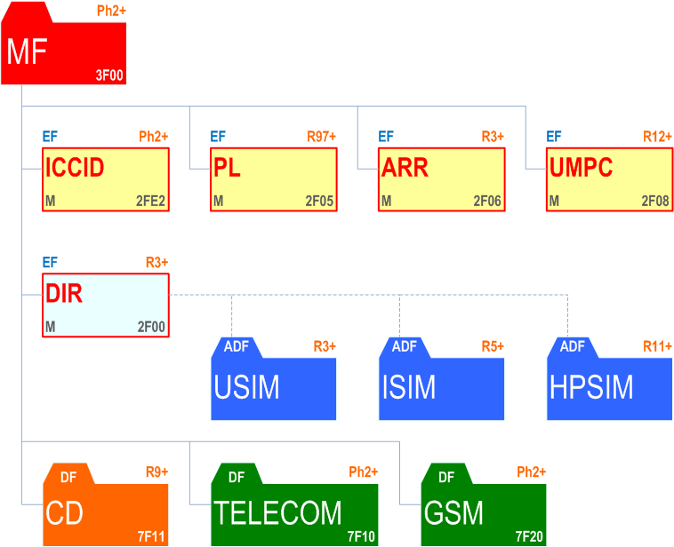
essential Table of Contents for ETSI TS 102 221 PDF version: 18.2.0
each title, in the "available" or "not available yet" area, links to the equivalent title in the CONTENT
![]()
![]()