Content for TS 23.468 Word version: 18.0.0
5.3 Service Continuity
5.3.1 General
5.3.2 Switching from Unicast Delivery to MBMS Delivery
5.3.3 Switching from MBMS Delivery to Unicast Delivery
5.4 Priority and Pre-emption for Group Communication
5.5 Charging
5.6 Security
5.3 Service Continuity p. 22
5.3.1 General p. 22
This clause provides flows & procedures for switching from Unicast Delivery to MBMS Delivery and vice-versa. In the flows, the need for service continuity is determined and executed by the UE. In the make-before-break flows, the UE may simultaneously receive the same DL data on both Unicast and MBMS bearers. In such scenarios, it is up to the application to manage duplicate detection.
5.3.2 Switching from Unicast Delivery to MBMS Delivery p. 22
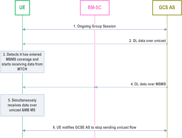
Figure 5.3.2-1 shows the procedures for service continuity when a UE which is receiving DL data over unicast moves into MBMS coverage. During the switching process, the UE simultaneously receives data from both unicast and MBMS, so there is no service interruption.

Step 1.
The UE has an on going group communication and the GCS AS informs the UE, over GC1, of the availability of MBMS delivery and of the corresponding TMGI of the MBMS bearer service.
Step 2.
The UE is receiving downlink data by Unicast Delivery.
Step 3.
The UE detects it has entered MBMS coverage and starts receiving MBMS Scheduling Information over MCH and the data from the MBMS bearer corresponding to the TMGI over MTCH.
Step 4.
The UE receives DL data by MBMS Delivery.
Step 5.
The UE simultaneously receives data by Unicast Delivery and MBMS Delivery.
Step 6.
The UE notifies the GCS AS via GC1 that it is in MBMS coverage and receiving the MBMS bearer service corresponding to the TMGI. The GCS AS stops sending the data over by Unicast Delivery to this UE. The UE now receives the content only by MBMS Delivery.
5.3.3 Switching from MBMS Delivery to Unicast Delivery p. 23
5.3.3.1 General p. 23
This clause defines the following two procedures for service continuity for switching from MBMS Delivery to Unicast Delivery:
- MBMS Delivery to Unicast Delivery (make-before-break).
- MBMS Delivery to Unicast Delivery (break-before-make).
5.3.3.2 MBMS Delivery to Unicast Delivery (make-before-break) p. 23
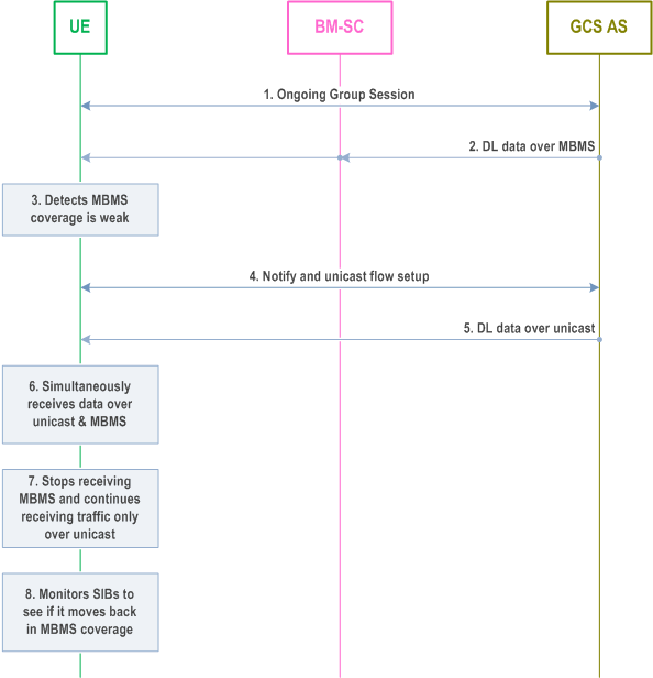
Figure 5.3.3.2-1 shows the procedure for service continuity when a UE is about to move out of MBMS coverage. In this procedure, the UE detects that is about to move out of MBMS coverage and elects to receive data over unicast while still within MBMS coverage. During the switching process, the UE simultaneously receives data from both unicast and MBMS, so there is no service interruption.

Step 1.
The UE has an ongoing group communication.
Step 2.
The UE is receiving downlink data by MBMS Delivery.
Step 3.
The UE detects that it is about to move out from MBMS coverage, for the corresponding MBMS bearer service, through implementation-specific methods. For example, the UE can determine it is about to move out of MBMS coverage by detecting poor MBSFN signal quality.
Step 4.
The UE notifies the GCS AS that it may move out of MBMS coverage via GC1 and the GCS AS sets up a unicast flow.
Step 5.
The GCS AS now sends the downlink data by Unicast Delivery to this UE.
Step 6.
The UE simultaneously receives DL data by Unicast Delivery and by MBMS Delivery.
Step 7.
The UE ceases to receive the downlink data by MBMS Delivery but continues receiving data by Unicast Delivery.
Step 8.
The UE monitors the SIBs in order to detect the TMGI on MCCH and thus determine it is back in MBMS coverage for the MBMS bearer service.
5.3.3.3 MBMS Delivery to Unicast Delivery (break-before-make) p. 25
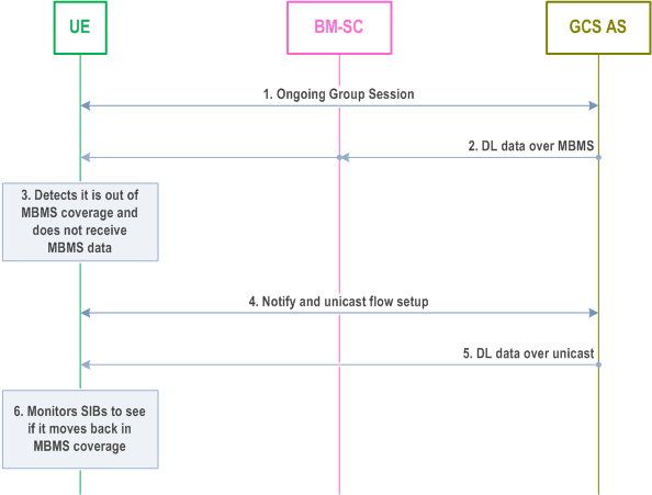
Figure 5.3.3.3-1 shows the procedure for service continuity when a UE has moved out of MBMS coverage. Here the UE starts receiving DL data over unicast after it has stopped receiving data over MBMS, so there may be some service interruption.
This procedure is used by the UE to handle loss of MBMS Delivery due to MBMS resource congestion in E-UTRAN resulting in pre-emption of the MBMS bearer service as described in clause 5.4.

Step 1.
The UE has an ongoing group communication.
Step 2.
The UE is receiving downlink data by MBMS Delivery for an MBMS bearer service is identified by a TMGI.
Step 3.
The UE detects it is out of MBMS coverage for that TMGI and, therefore, is unable to receive any data by MBMS Delivery for the corresponding MBMS bearer service.
Step 4.
The UE notifies the GCS AS via GC1 that it has moved out of MBMS coverage for the MBMS bearer service corresponding to the TMGI and the GCS AS sets up a unicast flow.
Step 5.
The GCS AS sends the downlink data by Unicast Delivery.
Step 6.
The UE monitors the SIBs in order to detect the TMGI on MCCH and thus determine that it is back in MBMS coverage for the MBMS bearer service.
5.4 Priority and Pre-emption for Group Communication p. 25
A Group Communication Session that requires to be prioritized over other Group Communication Sessions or non-Group Communication Sessions includes both the priority level and the GCS identifier in a service authorization request to the PCRF and to the BM-SC.
The priority level and the GCS identifier are defined at the application layer for priority and pre-emption purposes. The GCS AS provides the priority level and the GCS identifier to the PCRF and the BM-SC. It is mapped by the PCRF and the BM-SC to the ARP priority level, pre-emption capability and pre-emption vulnerability indication under the consideration of the respective EPS network.
In the case of Unicast Delivery, the PCRF translates the service characteristics to PCC policies and forwards its policy decision to the PCEF. The PCEF determines, based on policies provided by the PCRF, whether the PCEF modifies already established bearers or whether the PCEF establishes dedicated bearer(s) with the determined bearer characteristics. If the priority of a particular application Group Communication session changes, the GCS AS provides an update of the service characteristics towards the PCRF via the Rx interface. The PCRF updates the PCC policies and forwards them to the PCEF. The PCEF modifies already established bearers or establishes dedicated bearer(s) accordingly.
The PCRF shall, at the reception of service authorization from the GCS AS including an indication that is a prioritized GC Session and priority level, ensure that the ARP priority level of the default bearer is assigned a prioritized value which is at least as high as the highest priority of all Group Communication Sessions within the same IP-CAN session. The PCRF shall also ensure that the ARP pre-emption capability and pre-emption vulnerability indication of the default bearer satisfies the strongest requirements of all Group Communication Sessions within the same IP-CAN session.
When the PCRF detects that all prioritized Group Communication Sessions within the same IP-CAN session are released, the PCRF shall assign the ARP of the default bearer as appropriate.
In the case of MBMS Delivery, if the priority of an MBMS bearer needs to be changed, based upon a GCS AS decision to change the priority level, the GCS AS performs either:
- The Modify MBMS Bearer procedure in clause 5.1.2.4; or
- A new Activate MBMS Bearer procedure and a Deactivate MBMS Bearer procedure replacing the old MBMS bearer service with a new one.
- In the case of Unicast Delivery, the GCS AS is notified by the PCRF of unicast bearer release.
- In the case of MBMS Delivery, the related MBMS bearer may be 'suspended' by E-UTRAN and the UE becomes aware in either of the following ways:
- packets are dropped at the eNB. In this case the UE can detect that MBMS delivery is no longer available when the related TMGI is removed from MCCH.
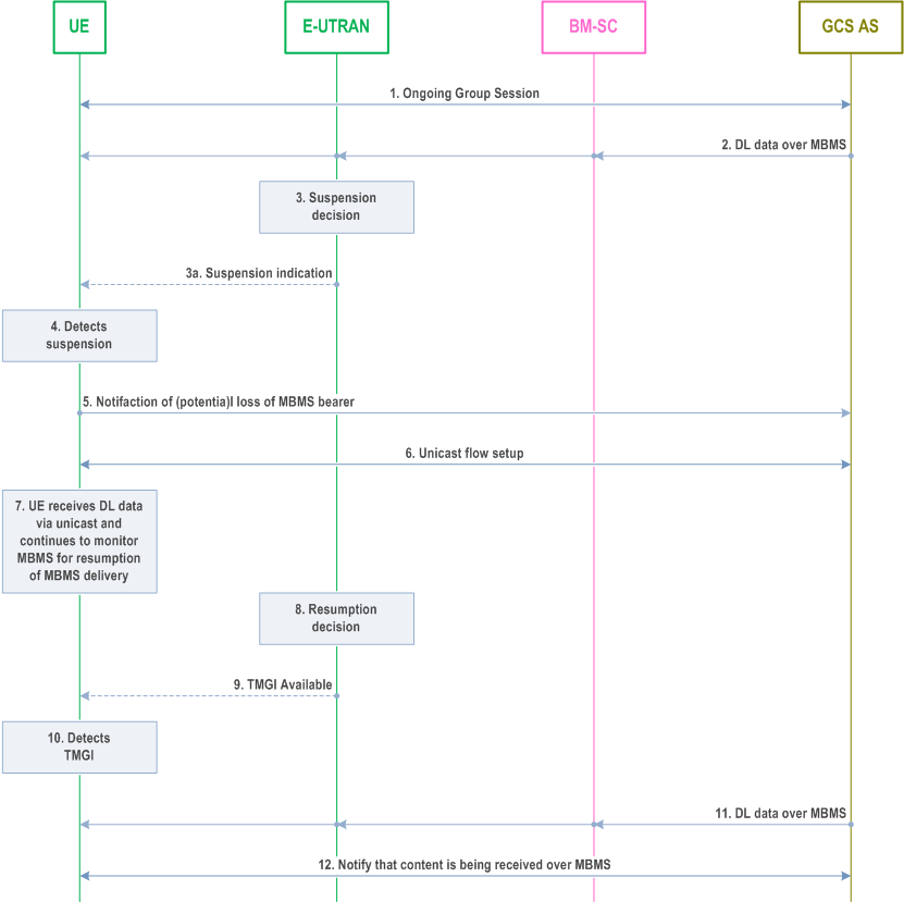
- The UE receives an explicit indication broadcast from the eNB in the MBMS Scheduling Information (see TS 36.300 and TS 36.321), where it is informed that transmission for the MBMS bearer is going to be, or has been, suspended. The procedure used by the UE in these scenarios is depicted in Figure 5.4-1.

Step 1.
The UE has an ongoing group communication.
Step 2.
The UE is receiving downlink data by MBMS Delivery.
Step 3.
E-UTRAN (e.g. after detecting MBMS congestion) decides to suspend one or more MBMS bearer(s) within MBSFN area(s) (based on e.g. the ARP and/or on the counting results for the corresponding MBMS service(s)), and trigger the migration of impacted UEs to receive DL data via unicast, by either:
Step 4.
- explicitly informing those UEs that the MBMS bearer has been, or is going to be, suspended by broadcasting an indication within MAC MBMS Scheduling Information (and removing the TMGI from the MCCH), or
- removing the TMGI of the MBMS bearer that has been suspended from the MCCH.
The UE detects the suspension of the corresponding MBMS bearer service, but continues to monitor for MBMS Delivery (i.e. because while it is establishing unicast there may still be DL data sent on the MBMS bearer).
Step 5.
Over GC1, the UE notifies the GCS AS of the MBMS service suspension.
Step 6.
The GCS AS decides whether to set up the Unicast Delivery path for the downlink data to this UE.
Step 7.
The UE receives DL data by Unicast Delivery and continues to monitor MBMS channels for resumption of the MBMS bearer.
Step 8.
At some point, the RAN determines that it can resume the MBMS bearer within the MBSFN area(s), e.g. when the congestion is over. The decision which of the suspended MBMS bearers to resume may be based on e.g. the ARP and/or on the counting results for the corresponding MBMS service(s).
Step 9.
The MCCH indicates that the TMGI is available.
Step 10.
The UE detects the TMGI on the MCCH and prepares to receive it.
Step 11.
The UE is again receiving downlink data by MBMS Delivery.
Step 12.
The UE notifies the GCS AS that it is receiving the group content via MBMS.
Step 13.
GCS AS stops the delivery via unicast.
5.5 Charging p. 28
For MBMS Delivery, the architecture requirement for charging defined for MBMS broadcast service for E-UTRAN in TS 23.246 shall apply.
For Unicast Delivery, the architecture requirement for charging defined for EPS bearer services in TS 23.401 shall apply.
5.6 Security p. 28
Security requirements for supporting the MB2 reference point for GCS are defined in TS 33.246.
No additional security requirement is defined for supporting GCS with Unicast Delivery.