Content for TS 23.303 Word version: 18.0.0
5.4 Procedures for ProSe Direct Communication
5.4.1 One-to-many ProSe Direct Communication general
5.4.2 One-to-many ProSe Direct Communication transmission
5.4.3 One-to-many ProSe Direct Communication reception
5.4.4 Direct communication via ProSe UE-to-Network Relay
5.4.4.1 General
5.4.4.2 IPv6 Stateless Address auto-configuration
5.4.4.3 IPv4 Address allocation using DHCPv4
5.4.4.4 TMGI advertisement and eMBMS traffic relay
5.4.4.5 Cell ID announcement procedure
5.4.5 One-to-one ProSe Direct Communication
5.4.5.1 General
5.4.5.2 Establishment of secure layer-2 link over PC5
5.4.5.3 Layer-2 link maintenance over PC5
5.4.5.4 Layer-2 link release over PC5
5.4.6 ProSe Per-Packet Priority
5.4.7 ProSe Per-Packet Reliability
...
...
5.4 Procedures for ProSe Direct Communication p. 102
5.4.1 One-to-many ProSe Direct Communication general p. 102
One-to-many ProSe Direct Communication is applicable only to ProSe-enabled Public Safety UEs and when authorised, can apply when the UE is served by E-UTRAN and when the UE is outside of E-UTRA coverage.
One-to-many ProSe Direct Communication has the following characteristics:
- One-to-many ProSe Direct Communication is connectionless. Thus there is no signalling over PC5 control plane.
- The radio layer provides a user plane communication service for transmission of IP packets between UEs engaged in direct communication.
- Members of a group share a secret from which a group security key may be derived to encrypt all user data for that group.
- Authorisation for one-to-many ProSe Direct Communication is configured in the UE by the ProSe Function using PC3 reference point.
- ProSe UE configuration parameters (e.g. including ProSe Group IP multicast addresses, ProSe Group IDs, Group security material, radio related parameters) are configured in the UE.
5.4.2 One-to-many ProSe Direct Communication transmission p. 103
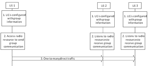
This procedure is applicable to authorized ProSe-enabled Public Safety UEs.
Step 1.
UE is configured with the related information for one-to-many ProSe Direct Communication as defined in clause 4.5.1.1.2.3.3. The UE obtains the necessary group context (ProSe Layer-2 Group ID, ProSe Group IP multicast address) to transmit IP-layer transport of data, and also the radio resource related parameters used for the Direct Communication.
Step 2.
The originating UE finds the appropriate radio resource to conduct one-to-many ProSe Direct Communication as specified in clause 4.5.1.1.2.3.1.
The protocol data unit passed for transmission to the Access Stratum is associated with:
Step 3.
- a Layer-3 protocol data unit type. In this release of the specification the following Layer-3 protocol data types are supported for one-to-many ProSe Direct Communication: IP and Address Resolution Protocol (see RFC 826).
- the corresponding Source Layer-2 ID and Destination Layer-2 ID. The Source Layer-2 ID is set to the ProSe UE ID assigned from the ProSe Key Management Function. The Destination Layer-2 ID is set to the ProSe Layer-2 Group ID.
- the ProSe Per-Packet Priority associated with the protocol data unit.
The originating UE sends the IP data to the IP multicast address using the ProSe Layer-2 Group ID as Destination Layer-2 ID.
5.4.3 One-to-many ProSe Direct Communication reception p. 103
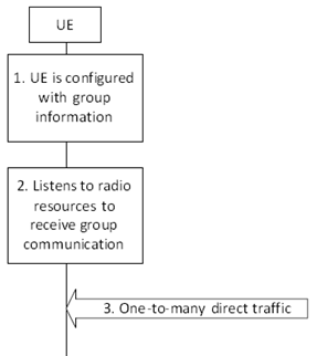
This procedure is only applicable to authorized ProSe-enabled Public Safety UEs.
Step 1.
UE is configured with the related information for one-to-many ProSe Direct Communication as defined in clause 4.5.1.1.2.3.3. The UE obtains the necessary group context (ProSe Layer-2 Group ID, Group IP multicast address) to receive IP-layer transport of data, and also the radio resource related parameters used for the Direct Communication.
Step 2.
The receiving UE listens to the allocated radio resource to receive one-to-many ProSe Direct Communication.
Step 3.
The receiving UE filters out the received frames based on the ProSe Layer-2 Group ID contained in the Destination Layer-2 ID and if it matches one of the configured Group IDs, it delivers the enclosed packet to the upper layers. The IP stack filters the received packets based on the Group IP multicast address.
The protocol data unit passed to the upper layers is associated with a Layer-3 protocol data unit type. In this release of the specification the following Layer-3 protocol data types are supported for one-to-many ProSe Direct Communication: IP and Address Resolution Protocol (see RFC 826).
5.4.4 Direct communication via ProSe UE-to-Network Relay |R13| p. 104
5.4.4.1 General p. 104
A ProSe UE-to-Network Relay capable UE may attach to the network (if it is not already connected) and connect to a PDN connection enabling the necessary relay traffic, or it may need to connect to additional PDN connection(s) in order to provide relay traffic towards Remote UE(s). PDN connection(s) supporting UE-to-Network Relay shall only be used for Remote ProSe UE(s) relay traffic.
Step 1.
The Remote UE Report message shall be sent when the Remote UE disconnects from the ProSe UE-to-Network Relay (e.g. upon explicit layer-2 link release or based on the absence of keep alive messages over PC5) to inform the MME and the S-GW and the P-GW that the Remote UE(s) have left.
In the case of Tracking Area Update involving MME change the Remote User IDs and related IP info corresponding to the connected Remote UEs are transferred to the new MME as part of the EPS bearer context transfer for the ProSe UE-to-Network Relay.
After being connected to the ProSe UE-to-Network Relay, the Remote UE keeps performing the measurement of the signal strength of the discovery message sent by the ProSe UE-to-Network Relay (i.e. the UE-to-Network Relay Discovery Announcement message in Model A or a UE-to-Network Relay Discovery Response message in Model B) for relay reselection as defined in TS 36.300. For Model B, to measure the PC5 link quality, the Remote UE sends a UE-to-Network Relay Discovery Solicitation message periodically. The message may contain a ProSe Relay UE ID of its serving ProSe UE-to-Network Relay. If the ProSe Relay UE ID is included in the message, then only the ProSe UE-to-Network Relay, which owns this ProSe Relay UE ID, shall respond to the UE-to-Network Relay Discovery Solicitation message.
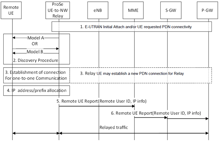
The ProSe UE-to-Network Relay performs initial E-UTRAN Attach (if not already attached) and/or establishes a PDN connection for relaying (if no appropriate PDN connection for this relaying exists). In case of IPv6, the ProSe UE-to-Network Relay obtains the IPv6 prefix via prefix delegation function from the network as defined in TS 23.401.
Step 2.
The Remote UE performs discovery of a ProSe UE-to-Network Relay using Model A or Model B discovery. The details of this procedure are described in clause 5.3.7.
Step 3.
The Remote UE selects a ProSe UE-to-Network Relay and establishes a connection for One-to-one ProSe Direct Communication. If there is no PDN connection associated with the ProSe Relay UE ID or an additional PDN connection for relaying is needed, the ProSe UE-to-Network Relay initiates a new PDN connection establishment procedure for relaying. The details of this procedure are described in clause 5.4.5.
Step 4.
IPv6 prefix or IPv4 address is allocated for the remote UE as it is specified in clause 5.4.4.2 and clause 5.4.4.3. From this point the uplink and downlink relaying can start.
Step 5.
The ProSe UE-to-Network Relay sends a Remote UE Report (Remote User ID, IP info) message to the MME for the PDN connection associated with the relay. The Remote User ID is an identity of the Remote UE user (provided via User Info) that was successfully connected in step 3. The MME stores the Remote User IDs and the related IP info in the ProSe UE-to-Network Relay's EPS bearer context defined in TS 23.401 for the PDN connection associated with the relay.
Step 6.
The MME forwards the Remote UE Report message to the S-GW and S-GW forwards the message to the P-GW of the UE-to-Network Relay UE. The MME may report multiple Remote UEs in one Remote UE Report message.
For IP info the following principles apply:
- for IPv4, the UE-to-network Relay shall report TCP/UDP port ranges assigned to individual Remote UE(s) (along with the Remote User ID);
- for IPv6, the UE-to-network Relay shall report IPv6 prefix(es) assigned to individual Remote UE(s) (along with the Remote User ID).
5.4.4.2 IPv6 Stateless Address auto-configuration p. 106
After the establishment the One-to-one ProSe Direct Communication the Remote UE may initiate the allocation of an IPv6 prefix as follows.
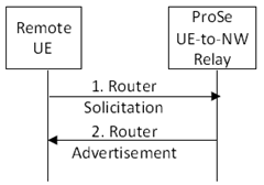
Figure 5.4.4.2-1: IPv6 prefix allocation using ProSe UE-to-Network Relay
(⇒ copy of original 3GPP image)
(⇒ copy of original 3GPP image)
Step 1.
If the Remote UE is configured to perform IPv6 Stateless Address auto-configuration, the Remote UE shall send a Router Solicitation message in order to solicit a Router Advertisement message as specified in RFC 4862. The message is sent using as Destination Layer-2 Address the ProSe Relay UE ID of the ProSe UE-to-Network Relay discovered during the establishment the One-to-one ProSe Direct Communication.
Step 2.
Upon receiving the Router Solicitation message from the UE the ProSe UE-to-Network Relay shall send an IPv6 Router Advertisement message as specified in RFC 4862 to the Remote UE. The ProSe UE-to-Network Relay acts as an advertising interface as specified in RFC 4861. The Router Advertisement messages shall contain the assigned IPv6 prefix. The ProSe UE-to-Network Relay shall obtain the IPv6 prefix assigned to the Remote UE via prefix delegation function from the network as defined in TS 23.401 before sending the IPv6 prefix to the Remote UE. After the Remote UE receives the Router Advertisement message, it constructs a full IPv6 address via IPv6 Stateless Address auto-configuration in accordance with RFC 4862. However, the Remote UE shall not use any identifiers defined in TS 23.003 as the basis for generating the interface identifier. For privacy, the Remote UE may change the interface identifier used to generate the full IPv6 address, as defined in TS 23.221 without involving the network. The Remote UE shall use the auto-configured IPv6 address while sending packets in this implicitly created PDN connection.
5.4.4.3 IPv4 Address allocation using DHCPv4 p. 107
After the establishment the One-to-one ProSe Direct Communication the Remote UE may initiate the allocation of an IPv4 address as follows.
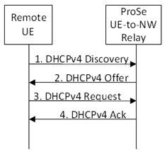
Figure 5.4.4.3-1: IPv4 address allocation using ProSe UE-to-Network Relay
(⇒ copy of original 3GPP image)
(⇒ copy of original 3GPP image)
Step 1.
After the UE releases the IPv4 address using DHCPv4 or the IPv4 address lease time expires, the same IPv4 address shall not be allocated to another Remote UE immediately by the ProSe UE-to-Network Relay.
If the Remote UE is configured to use IPv4, the Remote UE shall send DHCPv4 Discovery message. The message shall be sent using as Destination Layer-2 Address the ProSe Relay UE ID of the ProSe UE-to-Network Relay discovered during the establishment the One-to-one ProSe Direct Communication.
Step 2.
The ProSe UE-to-Network Relay acting as a DHCPv4 Server sends the DHCPv4 Offer with the assigned Remote UE IPv4 address. The IPv4 address provided to the Remote UE from the ProSe UE-to-Network Relay shall correspond to a local IPv4 address range configured in the ProSe UE-to-Network Relay.
Step 3.
When the Remote UE receives the lease offer, it sends a DHCP REQUEST message containing the received IPv4 address.
Step 4.
The ProSe UE-to-Network Relay acting as DHCPv4 server sends a DHCPACK message to the Remote UE. This message includes the lease duration and any other configuration information that the client might have requested.
On receiving the DHCPACK message, the Remote UE completes the TCP/IP configuration process.
5.4.4.4 TMGI advertisement and eMBMS traffic relay p. 107
The following procedure illustrated in Figure 5.4.4.4-1 is used by a ProSe-enabled Public safety UE to request a ProSe UE-to-Network Relay to start monitoring a specific TMGI availability and that the ProSe UE-to-Network Relay broadcasts this TMGI and its corresponding ProSe Layer-2 Group ID by using Relay Discovery Additional Information sent on the discovery transport, when it is detected on the MCCH of the serving cell. The eMBMS traffic related to this TMGI, if available, is also forwarded to the remote UE's served by the relay over a one-to-many link identified by a specific ProSe Layer-2 Group ID provided by the Relay when the procedure is executed.
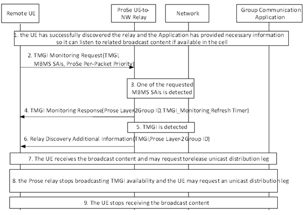
Step 1.
The UE has successfully discovered the ProSe UE-to-Network Relay and has obtained (perhaps after a one to one communication sessions with the relay) from a Group communication application the related service description that contains the TMGI, QCI, radio frequencies, and MBMS SAIs the UE should use to receive related eMBMS content. This interaction can happen before or after the UE has joined the relay. The application layer in the UE sets the ProSe Per-Packet Priority associated with the TMGI.
Step 2.
The UE sends to the ProSe UE-to-Network Relay a TMGI Monitoring Request (TMGI, MBMS SAIs, ProSe Per-Packet Priority) where the TMGI value, MBMS SAIs and ProSe Per-Packet Priority are obtained at step 1.
Step 3.
The ProSe UE-to-Network Relay retrieves the list of MBMS SAIs from the system information of the cell camped on as specified in TS 36.331 and checks whether at least one of the MBMS SAIs obtained at step 2 is included in the MBMS SAI list.
Step 4.
If the ProSe UE-to-Network Relay detects at least one of the request MBMS SAIs, the ProSe UE-to-Network Relay acknowledges the request with a TMGI Monitoring Response ( ProSe Layer 2 Group ID, TMGI_Monitoring_Refresh Timer, SAI indicator = true). The ProSe Layer 2 Group ID is used to forward to Remote UEs the eMBMS content related to the TMGI value received at step 2. The TMGI_Monitoring_Refresh Timer (configurable in the ProSe UE-to-Network Relay) is provided to the UE so that when this timer elapses the UE shall execute the TMGI monitoring request procedure if it still needs to monitor the TMGI. If a UE does not execute the TMGI Monitoring Request procedure when this TMGI_Monitoring_Refresh Timer expires in the UE and no other UE executes the refresh procedure for this TMGI, then when the TMGI_Monitoring_Refresh Timer for the TMGI expires in the relay, the relay shall stop monitoring the TMGI and also to forward any related content if it was doing so. If the ProSe UE-to-Network Relay is not in the coverage of any requested SAIs, the SAI indicator is set to false and the ProSe UE-to-Network Relay remains monitoring the TMGI until the TMGI_Monitoring_Refresh Timer expires. It is assumed that bearer level security is not applied to PC5 ProSe one-to-may link for MBMS traffic relay.
Step 5.
The ProSe UE-to-Network Relay detects the TMGI it has been requested to monitor.
Step 6.
Upon detection of the TMGI, the ProSe UE-to-Network Relay broadcasts availability of the TMGI and the corresponding ProSe Layer 2 Group ID by sending a Relay Discovery Additional Information Message (TMGI, ProSe Layer 2 Group ID) as defined in clause 4.6.4.10. This is repeated with a configurable (in the ProSe UE to Network Relay) repetition interval which should normally be smaller than the TMGI_Monitoring_Refresh Timer. The value of the TMGI may be used by devices discovering the UE-to-Network Relay as a preference criterion for Relay selection, if they are interested in the TMGI the relay is advertising.
Step 7.
The UE detects the announcement of step 6 and subsequently starts to receive the broadcast content on the PC5 ProSe one-to-many link associated to the Prose Layer-2 Group ID defined at step 4, and may request to release unicast distribution leg if any was being used. The ProSe UE-to-Network Relay applies the received ProSe Per-Packet Priority value in step 2 to transmit the eMBMS traffic over the PC5 interface. For a given TMGI, if different ProSe Per-Packet Priority values are received from different UEs, the ProSe Per-Packet Priority that the UE-to-Network Relay determines to use for transmitting the eMBMS data associated with the TMGI is up to UE implementation.
Step 8.
Upon detection of loss of TMGI, the ProSe UE-to-Network Relay stops broadcasting availability of the TMGI. Optionally, it also sends a positive indication of loss of TMGI so as to accelerate loss of TMGI detection in the UE (not shown in the procedure). The UE may request a unicast distribution leg from the GCS AS.
Step 9.
The UE stops receiving the broadcast content on the PC5 ProSe one-to-many link associated to the Prose Layer Group-2 ID defined at step 4.
5.4.4.5 Cell ID announcement procedure p. 109
The following procedure outlined in figure 5.4.4.5-1 allows an authorized ProSe-enabled Public safety UE, based on application requirements outside the scope of the present procedure, to request a ProSe UE-to-Network Relay to announce the EUTRAN Cell Global ID (ECGI) of the Cell serving the ProSe UE-to-Network Relay.
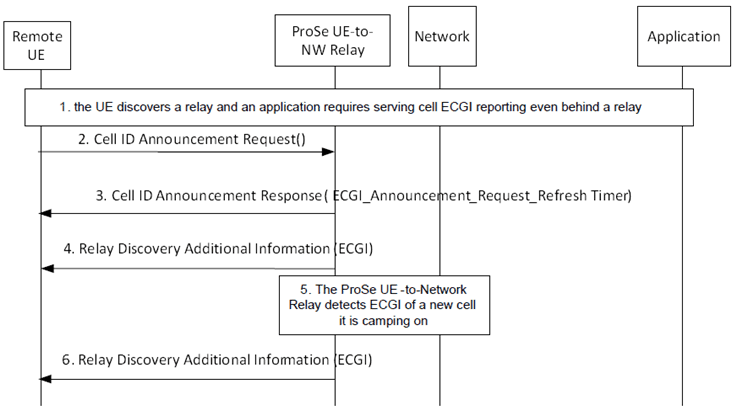
Step 1.
A UE has discovered a ProSe UE-to-Network Relay and an application requires serving cell ECGI reporting even when it is behind a relay (i.e. the application benefits from this value even if it is the value of the cell serving the relay and not the UE directly).
Step 2.
The UE sends to the ProSe UE-to-Network Relay a Cell ID Announcement Request() to support the needs of such application
Step 3.
The ProSe UE-to-Network Relay acknowledges receipt of the request in step 2 with a Cell ID Announcement Response (ECGI_Announcement_Request_Refresh Timer). The ECGI_Announcement_Request_Refresh Timer, (configurable in the ProSe UE-to-Network Relay) is provided to the UE so that when this timer elapses the UE shall repeat the Cell ID Announcement Request procedure if it still needs obtain the ECGI. If a UE does not execute the Cell ID Announcement Request procedure when this ECGI_Announcement_Request_Refresh Timer expires and no other UE request ECGI announcement before the ECGI_Announcement_Request_Refresh timer expires in the ProSe UE-to-Network Relay, then the relay shall stop announcing the ECGI of the serving cell.
Step 4.
The ProSe UE-to-Network Relay announces the ECGI of the serving cell by sending Relay Discovery Additional Information Message (ECGI) as defined in clause 4.6.4.10. This is repeated periodically with a configurable frequency (normally Higher than the one related to the ECGI_Announcement_Request_Refresh Timer) until there is no UE requesting to announce the ECGI as determined by the ECGI_Announcement_Request_Refresh Timer running in the ProSe UE-to-Network Relay.
Step 5.
The ProSe UE-to-Network Relay may at any time detect the ECGI of a new serving cell it is happening to be camping on.
Step 6.
Step 5 triggers the ProSe UE-to-Network Relay to announce the ECGI of the serving cell by sending a Relay Discovery Additional Information Message (ECGI) immediately and repeat it periodically with a configurable frequency as in step 4 until there is no UE requesting to announce the ECGI as determined by the ECGI_Announcement_Request_Refresh Timer running in the ProSe UE-to-Network Relay.
5.4.5 One-to-one ProSe Direct Communication |R13| p. 110
5.4.5.1 General p. 110
One-to-one ProSe Direct Communication is realised by establishing a secure layer-2 link over PC5 between two UEs.
Each UE has a Layer-2 ID for unicast communication that is included in the Source Layer-2 ID field of every frame that it sends on the layer-2 link and in the Destination Layer-2 ID of every frame that it receives on the layer-2 link.
The UE needs to ensure that the Layer-2 ID for unicast communication is at least locally unique. To that effect the UE should be prepared to handle Layer-2 ID conflicts with adjacent UEs using unspecified mechanisms (e.g. self-assign a new Layer-2 ID for unicast communication when a conflict is detected).
The layer-2 link for one-to-one ProSe Direct Communication is identified by the combination of the Layer-2 IDs of the two UEs. This means that the UE can engage in multiple layer-2 links for one-to-one ProSe Direct Communication using the same Layer-2 ID.
5.4.5.2 Establishment of secure layer-2 link over PC5 p. 110
Depicted in figure 5.4.5.2-1 is the procedure for establishment of secure layer-2 link over PC5.
UEs engaged in isolated (non-relay) one to one communication negotiate IP address allocation mechanisms and optionally exchange link-local IPv6 addresses if needed during the link establishment procedure.
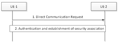
Step 1.
UE-1 sends a Direct Communication Request message to UE-2 in order to trigger mutual authentication. This message includes the User Info.
If the link is setup for isolated one-to-one communication (none of the UEs is a relay), UE-1 shall indicate in the message whether it can act as a DHCPv4 server, IPv6 router, or both. If UE-1 does not support any of the IP address allocation mechanisms, it shall include a link-local IPv6 address in the message.
Step 2.
UE-2 initiates the procedure for mutual authentication. The successful completion of the authentication procedure completes the establishment of the secure layer-2 link over PC5. As part of this step, UE-2 includes the User Info in a response to UE-1.
If the link is setup for isolated one-to-one communication (none of the UEs is a relay), UE-2 shall indicate to UE-1 in the response message whether it can act as a DHCPv4 server, IPv6 router, or both. If UE-2 does not support any of the IP address allocation mechanisms and UE-1 included a link-local IPv6 address in step 1, UE-2 shall include a non-conflicting link-local IPv6 address in the response message.
If both UE-1 and UE-2 selected to use link-local IPv6 address, they shall disable the duplicate address detection defined in RFC 4862.
5.4.5.3 Layer-2 link maintenance over PC5 p. 111
The PC5 Signalling Protocol shall support keep-alive functionality that is used to detect that when the UEs are not in ProSe Communication range, so that they can proceed with implicit layer-2 link release.
5.4.5.4 Layer-2 link release over PC5 p. 111
Depicted in Figure 5.4.5.4-1 is layer-2 link release procedure over PC5. This procedure can be also used to release the layer-2 link between the Remote UE and the UE-to-Network Relay, initiated by either the Remote UE or the Relay e.g. due to temporary loss of connectivity to the network, battery running low of the relay, etc.
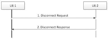
Step 1.
UE-1 sends a Disconnect Request message to UE-2 in order to release the layer-2 link and deletes all context data associated with.
Step 2.
Upon reception of the Disconnect Request message UE-2 responds with a Disconnect Response message and deletes all context data associated with the layer-2 link.
5.4.6 ProSe Per-Packet Priority |R13| p. 112
5.4.6.1 General p. 112
When the ProSe upper layer (i.e. above PC5 access stratum) passes a protocol data unit for transmission to the PC5 access stratum, the ProSe upper layer provides a ProSe Per-Packet Priority from a range of 8 possible values.
The ProSe Per-Packet Priority is independent of the Destination Layer-2 ID and applies to both one-to-one and one-to-many ProSe Direct Communication.
The ProSe Per-Packet Priority is selected by the application layer based on criteria that are outside the scope of this specification.
A ProSe Per-Packet Priority value shall be assigned to PC5-S messages. The UE is configured with one ProSe Per-Packet Priority value that is used for transmitting any of the PC5-S messages as described in clause 4.5.1.1.2.3.1.
The ProSe Per-Packet Priority is neutral to the mode in which the UE accesses the medium i.e. whether scheduled or autonomous transmission modes defined in TS 36.300 are used.
The ProSe access stratum uses the ProSe Per-Packet Priority associated with the protocol data unit as received from the upper layers to prioritise the transmission in respect with other intra-UE transmissions (i.e. protocol data units associated with different priorities awaiting transmission inside the same UE) and inter-UE transmissions (i.e. protocol data units associated with different priorities awaiting transmission inside different UEs).
Priority queues (both intra-UE and inter-UE) are expected to be served in priority order i.e. UE serves all packets associated with ProSe Per-Packet Priority N before serving packets associated with priority N+1 (lower number meaning higher priority).
5.4.6.2 ProSe UE-to-Network Relay p. 112
For unicast uplink traffic the ProSe UE-to-Network Relay uses the uplink TFTs to select the uplink EPS bearers for relayed uplink packets independently from the ProSe Per Packet Priority applied over PC5 by Remote UEs.
For unicast downlink traffic the ProSe UE-to-Network Relay maps the QCI of the EPS bearer into a ProSe Per-Packet Priority value to be applied for the downlink relayed unicast packets over PC5. The mapping rules are provisioned in the Relay UE.
For eMBMS traffic the ProSe UE-to-Network Relay uses the ProSe Per-Packet Priority that is requested for a specific TMGI by Remote UEs using PC5-S procedures to be applied for the multicast packets corresponding to that TMGI when they are relayed over PC5.
5.4.7 ProSe Per-Packet Reliability |R15| p. 112
5.4.7.1 General p. 112
When the ProSe upper layer (i.e. above PC5 access stratum) passes a protocol data unit for transmission to the PC5 access stratum, the ProSe upper layer provides a ProSe Per-Packet Reliability from a range of 8 possible values.
The ProSe Per-Packet Reliability is selected by the application layer based on criteria that are outside the scope of this specification.
The ProSe Per-Packet Reliability is neutral to the mode in which the UE accesses the medium i.e. whether scheduled or autonomous transmission modes defined in TS 36.300 are used.
The ProSe access stratum uses the ProSe Per-Packet Reliability associated with the protocol data unit as received from the upper layers to decide and adjust the transmission behaviour as defined in TS 36.300.