Content for TS 23.281 Word version: 19.2.0
1…
5…
6…
7…
7.1.2.3…
7.1.2.3.1.2…
7.1.2.3.2…
7.1.2.4…
7.1.2.5.2…
7.1.3…
7.2…
7.2.2.3…
7.2.2.4…
7.2.3…
7.3…
7.4…
7.4.3…
7.5…
7.5.2.3…
7.6…
7.7…
7.7.1.3…
7.7.1.3.2A…
7.7.1.3.4…
7.7.1.3.6…
7.7.2…
7.7.2.7…
7.7.2.9…
7.8…
7.11…
7.17…
7.19…
7.19.2.8…
7.19.3…
7.19.3.1.4…
7.19.3.2…
7.19.3.2.3…
7.19.3.2.6…
A…
7.7.1.3 Transmission control within one MC system for MCVideo service
7.7.1.3.1 Transmission control during an MCVideo session
7.7.1.3.2 Reception control during an MCVideo session
...
...
7.7.1.3 Transmission control within one MC system for MCVideo service p. 135
7.7.1.3.1 Transmission control during an MCVideo session p. 135
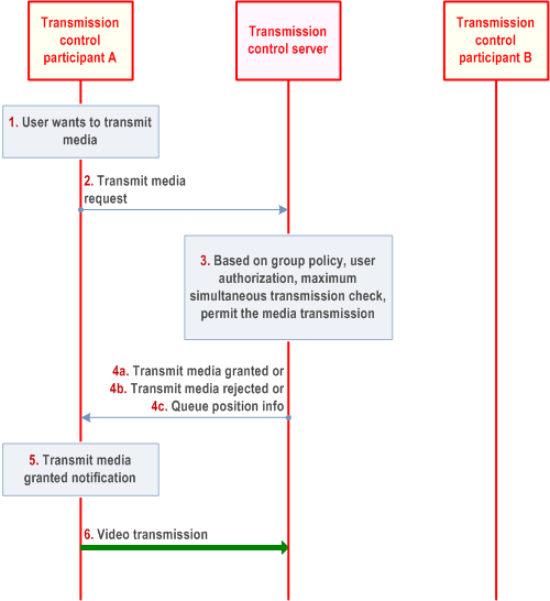
Figure 7.7.1.3.1-1 describes the procedure for transmission control between the transmission control participant and the transmission control server during an MCVideo session. Only two UEs involved in the session are shown for the simplicity.
Pre-condition:
- MCVideo session is established between MCVideo clients (client A and client B) and MCVideo server
- Transmission control is established between transmission control participants and transmission control server and there is no ongoing media transmission.

Step 1.
Transmission control participant A wants to send video media over the session.
Step 2.
Transmission control participant A sends a transmit media request message to transmission control server which includes transmission priority and other information as necessary.
Step 3.
Transmission control server makes the determination on what action (grant, deny, or queue) to take on the request based on transmission control criteria (e.g., group policy) and determines to accept the transmit media request from transmission control participant A.
Step 4.
Transmission control server responds with a transmit media granted message (4a) to transmission control participant A. Transmission control server may send transmit media rejected message (4b) indicating the cause of rejection or queue position info message (4c) indicating that the transmit media request has been queued.
Step 5.
The transmit media granted shall cause the user of UE A where the transmission control participant A is located to be notified.
Step 6.
Transmission control participant A starts sending video media over the session established to the transmission control server.
7.7.1.3.2 Reception control during an MCVideo session p. 136
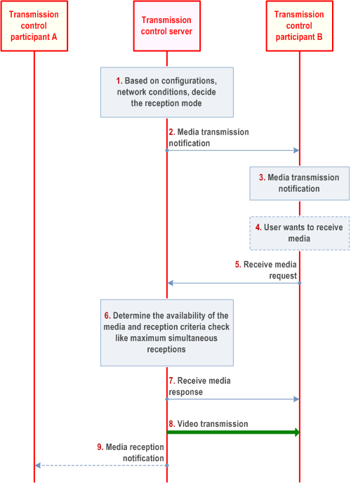
Figure 7.7.1.3.2-1 describes the procedure for the reception control between the transmission control participant and the transmission control server during an MCVideo session. Only two UEs involved in the session are shown for the simplicity.
Pre-condition:
- MCVideo session is established between MCVideo clients (client A and client B) and MCVideo server
- Transmission control is established between transmission control participants and transmission control server.
- Transmission control participant A has been granted the permission to transmit media.

Step 1.
The transmission control server determines the reception mode for downlink transmission control participants for the media transmission permitted to transmission control participant A. The manual and forced reception modes are determined based on configurations (e.g. auto-receive video transmissions, auto-receive emergency video transmissions) as described in Annex A.
Step 2.
Transmission control server sends a media transmission notification message to the transmission control participant B including information about the video transmitter and the reception mode.
Step 3.
The receipt of the media transmission notification is used to inform the user of UE B the details of video transmission and the video transmitter.
Step 4.
Based on the notification received, the user of UE B may want take actions (receive, reject or cancel) regarding the media available for reception.
Step 5.
If user of UE B wants to receive the media or it required to receive the media via forced reception, it causes the transmission control participant B to send a media receive request message to the transmission control server.
Step 6.
Transmission control server makes the determination on what action (e.g., real-time stream downlink, make stream downloadable, reject) to take on the request based on reception control criteria (e.g., allowed simultaneous reception) and determines to accept the media receive request from transmission control participant B. Transmission control server will also determine the availability of the media at the server to initiate the downlink reception.
Step 7.
Transmission control server sends a receive media response message to transmission control participant B.
Step 8.
Transmission control server sends video media to transmission control participant B.
Step 9.
Optionally, the transmission control server sends media reception notification message to transmission control participant A which includes the information about the video recipient (transmission control participant B).