Content for TS 38.106 Word version: 18.2.0
4 General
4.1 Relationship between Minimum Requirements and Test Requirements
4.2 Conducted and radiated requirement reference points
4.3 Repeater classes
4.4 Regional requirements
4.5 Applicability of requirements
4.6 Requirements for contiguous and non-contiguous spectrum
4.7 Requirements for repeater capable of multi-band operation
5 Operating bands
5.1 General
5.2 Operating bands
5.3 Channel arrangement
...
...
4 General p. 14
4.1 Relationship between Minimum Requirements and Test Requirements p. 14
Conformance to the present specification is demonstrated by fulfilling the test requirements specified in the conformance specification TS 38.115-1 [7] or TS 38.115-2 [8].
The minimum requirements given in this specification make no allowance for measurement uncertainty. The test specifications TS 38.115-1 [7] and TS 38.115-2 [8] define test tolerances. These test tolerances are individually calculated for each test. The test tolerances are used to relax the minimum requirements in this specification to create test requirements. For some requirements, including regulatory requirements, the test tolerance is set to zero.
The measurement results returned by the test system are compared - without any modification - against the test requirements as defined by the shared risk principle.
The shared risk principle is defined in recommendation ITU-R M.1545 [6].
4.2 Conducted and radiated requirement reference points p. 14
4.2.1 Repeater type 1-C p. 14
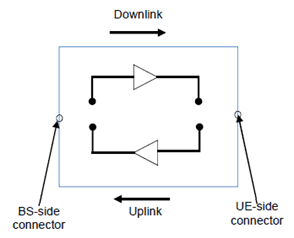
For repeater type 1-C, the requirements are applied at the repeater antenna connector (BS-side connector or UE-side connector) for downlink or uplink for the configuration in normal operating conditions.

4.2.2 Repeater type 2-O p. 15
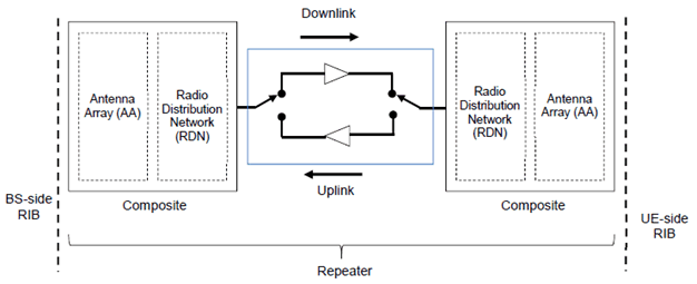
For repeater type 2-O, the radiated characteristics are defined over the air (OTA), where the operating band specific radiated interface is referred to as the Radiated Interface Boundary (RIB). Radiated requirements are also referred to as OTA requirements. The (spatial) characteristics in which the OTA requirements apply are detailed for each requirement.

4.3 Repeater classes p. 16
4.3.1 Repeater class for downlink p. 16
The requirements in this specification apply to downlink Wide Area repeaters, downlink Medium Range repeaters and downlink Local Area repeaters unless otherwise stated. The associated deployment scenarios for each class are exactly the same for repeater with and without connectors.
For repeater type 1-C and type 2-O, repeater downlink classes are defined as indicated below:
- Wide Area repeaters are characterised by requirements derived from Macro Cell scenarios with a repeater to UE minimum distance along the ground equal to 35 m.
- Medium Range repeaters are characterised by requirements derived from Micro Cell scenarios with a repeater to UE minimum distance along the ground equal to 5 m.
- Local Area repeaters are characterised by requirements derived from Pico Cell scenarios with a repeater to UE minimum distance along the ground equal to 2 m or from Femto Cell scenarios.
- Note: The requirements in this specification for LA 1-C repeaters apply to 1-C repeaters with declared output power less than or equal to LA rated output power limits as in Table 6.2.1-1.
4.3.2 Repeater class for uplink p. 16
The requirements in this specification apply to uplink Wide Area repeaters and uplink Local Area repeaters unless otherwise stated. The associated deployment scenarios for each class are exactly the same for repeater with and without connectors.
For repeater type 1-C and type 2-O, repeater uplink classes are defined as indicated below:
- Wide Area repeaters are characterised by requirements derived from Macro Cell and/or Micro Cell scenarios.
- Local Area repeaters are characterised by requirements derived from Pico Cell and/or Micro Cell scenarios.
4.4 Regional requirements p. 16
Some requirements in the present document may only apply in certain regions either as optional requirements, or as mandatory requirements set by local and regional regulation. It is normally not stated in the 3GPP specifications under what exact circumstances the regional requirements apply, since this is defined by local or regional regulation.
Table 4.4-1 lists all requirements in the present specification that may be applied differently in different regions.
| Clause number | Requirement | Comments |
|---|---|---|
| 5.2 | Operating bands | Some NR operating bands may be applied regionally. |
| 6.2 | Repeater output power | For Band n41 and n90 operation in Japan, additional output power limits shall be applied. |
| 6.2.4, 7.3.4 | Repeater output power, OTA repeater output power: Additional requirements | These requirements may be applied regionally as additional repeater output power requirements. |
| 6.5.2 | Adjacent Channel Leakage Power Ratio | For Band n41 and n90 operation in Japan, absolute ACLR limits shall be applied to the sum of the absolute ACLR power over all antenna connectors for repeater type 1-C. |
| 6.5.3.2, 7.5.3.2 | Operating band unwanted emission, OTA operating band unwanted emissions | Category A or Category B operating band unwanted emissions limits may be applied regionally. |
| 6.5.3.2.5.1 | LOperating band unwanted emission | LThe repeater may have to comply with the additional requirements, when deployed in regions where those limits are applied, and under the conditions declared by the manufacturer. |
| 6.5.3.2.5.2 | LOperating band unwanted emission | LThe repeater operating in Band n20 may have to comply with the additional requirements for protection of DTT, when deployed in certain regions. |
| 6.5.3.2 | LOperating band unwanted emissions | LFor Band n41 and n90 operation in Japan, the operating band unwanted emissions limits shall be applied to the sum of the emission power over all antenna connectors for repeater type 1-C. |
| 6.5.4.2.1, 7.5.4.2 | LTx spurious emissions, OTA Tx spurious emissions | LCategory A or Category B spurious emission limits, as defined in ITU-R Recommendation SM.329 [5], may apply regionally. |
| 6.5.4.2.2, 7.5.4.2.3 | LTx spurious emissions: additional requirements, OTA Tx spurious emissions: additional requirements | LThese requirements may be applied for the protection of system operating in frequency ranges other than the repeater operating band. |
| 6.5.4.2 | LTransmitter spurious emissions | LFor Band n41 and n90 operation in Japan, the sum of the spurious emissions over all antenna connectors for repeater type 1-C shall not exceed the basic limits. |
| 6.5.5.1 | LReceiver spurious emissions | LFor Band n41 and n90 operation in Japan, the sum of receiver spurious emissions requirements over all antenna connectors for repeater type 1-C shall not exceed minimum requirements defined in clause 6.5.5.2. |
| 6.7.2 | LInput intermodulation | LInterfering signal positions that are partially or completely outside of any downlink operating band of the repeater are not excluded from the requirement in Japan in Band n77, n78, n79. |
| 6.8 | Output intermodulation | For Band n41 and n90 operation in Japan, the repeater may have to comply with the additional requirements, when deployed in certain regions. |
4.5 Applicability of requirements p. 17
In Table 4.5-1, the requirement applicability for each requirement set is defined. For each requirement, the applicable requirement clause in the specification is identified. Requirements not included in a requirement set is marked not applicable (NA).
| Requirement | Requirement set | |
|---|---|---|
| Repeater type 1-C | Repeater type 2-O | |
| Repeater output power | 6.2 | NA |
| Frequency stability | 6.3 | |
| Out of band gain | 6.4 | |
| Unwanted emissions | 6.5 | |
| Error Vector Magnitude | 6.6 | |
| Input intermodulation | 6.7 | |
| Output intermodulation | 6.8 | |
| Adjacent Channel Rejection Ratio (ACRR) | 6.9 | |
| Transmit ON/OFF power | 6.10 | |
| Repeater output power | NA | 7.2 |
| OTA frequency stability | 7.3 | |
| OTA out of band gain | 7.4 | |
| OTA unwanted emissions | 7.5 | |
| OTA Error Vector Magnitude | 7.6 | |
| OTA input intermodulation | 7.7 | |
| OTA Adjacent Channel Rejection Ratio (ACRR) | 7.8 | |
| OTA transmit ON/OFF power | 7.9 | |
4.6 Requirements for contiguous and non-contiguous spectrum p. 18
A spectrum allocation where a repeater operates can either be contiguous or non-contiguous. Unless otherwise stated, the requirements in the present specification apply for repeater configured for both contiguous spectrum operation and non-contiguous spectrum operation.
For repeater operation in non-contiguous spectrum, some requirements apply at the repeater passband edges. For each such requirement, it is stated how the limits apply relative to the repeater gap between passbands and the Inter-passband gap respectively.
4.7 Requirements for repeater capable of multi-band operation p. 18
For multi-band connector or multi-band RIB, the RF requirements in clauses 6 and 7 apply separately to each supported operating band unless otherwise stated. For some requirements, it is explicitly stated that specific additions or exclusions to the requirement apply at multi-band connector(s), and multi-band RIB(s) as detailed in the requirement clause. For repeater capable of multi-band operation, various structures in terms of combinations of different downlink and uplink implementations (multi-band or single band) with mapping to one or more antenna connectors for repeater type 1-C in different ways are possible. For multi-band connector(s) the exclusions or provisions for multi-band apply. For single-band connector(s), the following applies:
- Single-band transmitter spurious emissions, operating band unwanted emissions, ACLR, output intermodulation, ACRR and receiver spurious emissions requirements apply to this connector that is mapped to single-band.
- If the repeater is configured for single-band operation, single-band requirements shall apply to this antenna connector configured for single-band operation and no exclusions or provisions for multi-band capable repeater are applicable. Single-band requirements are tested separately at the antenna connector configured for single-band operation, with all other antenna connectors terminated.
5 Operating bands p. 19
5.1 General p. 19
The channel arrangements presented in this clause are based on the operating bands defined in the present release of specifications.
Requirements throughout the RF specifications are in many cases defined separately for different frequency ranges (FR). The frequency ranges in which NR can operate according to the present version of the specification are identified as described in Table 5.1-1.
| Frequency range designation | Corresponding frequency range | |
|---|---|---|
| FR1 | 410 MHz - 7125 MHz | |
| FR2 | FR2-1 | 24250 MHz - 52600 MHz |
| FR2-2 | 52600 MHz - 71000 MHz | |
Whenever FR2 is referred, both FR2-1 and FR2-2 frequency sub-ranges shall be applied, unless otherwise stated.
5.2 Operating bands p. 19
NR repeater is designed to operate in the operating bands in FR1 and FR2-1 defined in TS 38.104 except the operating bands n46, n96 and n102.
5.3 Channel arrangement p. 19
5.3.1 Channel raster p. 19
5.3.1.1 NR-ARFCN and channel raster p. 19
The NR-ARFCN and channel raster is the same as specified for BS in subclause 5.4.2.1 of TS 38.104.
5.3.1.2 Channel raster entries for each operating band p. 19
The channel raster entries for NR bands for FR1 and FR2-1 defined in TS 38.104 are the same as specified for BS in clause 5.4.2.3 of TS 38.104.
5.3.2 Synchronization raster p. 19
5.3.2.1 Synchronization raster and numbering p. 19
The synchronization raster and numbering are the same as specified for BS in clause 5.4.3.1 of TS 38.104.
5.3.2.2 Synchronization raster entries for each operating band p. 20
The synchronization raster entries for NR bands for FR1 and FR2-1 defined in TS 38.104 are the same as specified for BS in clause 5.4.3.3 of TS 38.104.