Content for TS 26.131 Word version: 18.1.0
0…
5…
5.4…
5.4.3…
5.4.5…
5.4.7…
5.5…
5.8…
5.12…
6…
6.4…
6.4.3…
6.4.5…
6.4.7…
6.5…
6.8…
6.11…
6.12…
7…
7.4…
7.5…
7.8…
7.11…
7.12…
8…
8.4…
8.5…
8.8…
8.11…
8.12…
7.4 Sensitivity/frequency characteristics
7.4.0 General
7.4.1 Handset and headset UE sending
7.4.2 Handset and headset UE receiving
7.4.3 Desktop hands-free UE sending
7.4.4 Desktop hands-free UE receiving
7.4.5 Hand-held hands-free UE sending
7.4.6 Hand-held hands-free UE receiving
7.4.7 Electrical interface UE sending
7.4.8 Electrical interface UE receiving
...
...
7.4 Sensitivity/frequency characteristics p. 68
7.4.0 General p. 68
It is recommended for all configurations (handset, headset etc) to have a flat sending frequency response in super-wideband mode.
Tolerance masks apply to the center frequencies of the fractional octave bands specified for the respective tests in TS 26.132.
7.4.1 Handset and headset UE sending p. 68
The sensitivity/frequency characteristics shall be as follows:
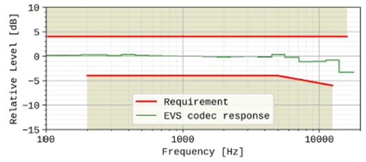
The sending sensitivity frequency response, measured either from the mouth reference point (MRP) to the digital interface or from the MRP to the SS audio output (digital output of the reference speech decoder of the SS), shall be within a mask, which can be drawn between the points given in Table 17.
The masks are drawn with straight lines between the breaking points in the tables on a logarithmic (frequency) - linear (dB sensitivity) scale.
| Frequency (Hz) | Upper limit (dB) | Lower limit (dB) |
|---|---|---|
| 100 | 4 | |
| 200 | 4 | -4 |
| 5000 | 4 | -4 |
| 12500 | 4 | -6 |
| 16000 | 4 | |
|
NOTE:
All sensitivity values are expressed in dB on an arbitrary scale.
|
||

Figure 15: Handset and headset sending sensitivity/frequency masks. The frequency response of the EVS codec operating as specified in TS 26.132 (super-wideband 24,4kbit/s, using the specified P.501 speech test signal), is plotted for reference, normalized to 0dB at 1kHz.
(⇒ copy of original 3GPP image)
(⇒ copy of original 3GPP image)
A UE operating in super-wideband mode shall pass the super-wideband requirements (i.e. when measured according to in 1/3rd octaves) as specified in Table 17, and shall also pass the wideband sensitivity/frequency characteristics requirements in the wideband range using the wideband measurement (i.e. measured in 1/12th octaves) as specified in Table 9.
Compliance shall be checked by the relevant test described in TS 26.132.
7.4.2 Handset and headset UE receiving p. 69
7.4.2.1 Handset UE receiving p. 69
The sensitivity/frequency characteristics shall be as follows:
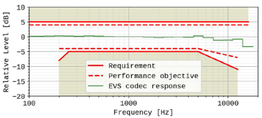
The receiving sensitivity frequency response, measured either from the digital interface to the DRP with diffuse-field correction or from the SS audio input (analogue or digital input of the reference speech encoder of the SS) to the DRP with diffuse-field correction, shall be within a mask, which can be drawn with straight lines between the breaking points in Table 19 on a logarithmic (frequency) - linear (dB sensitivity) scale.
| Frequency (Hz) | Upper limit (dB) | Lower limit (dB) |
|---|---|---|
| 100 | 5 | |
| 200 | 5 | -8 |
| 250 | 5 | -5 |
| 5000 | 5 | -5 |
| 16000 | 5 | |
| 12500 | 5 | -11 |
|
NOTE:
All sensitivity values are expressed in dB on an arbitrary scale.
|
||
It is desired as a performance objective that the receiving sensitivity/frequency response be within the mask which can be drawn with straight lines between the breaking points in Table 20.
| Frequency (Hz) | Upper limit (dB) | Lower limit (dB) |
|---|---|---|
| 100 | 4 | |
| 200 | 4 | -4 |
| 250 | 4 | -4 |
| 5000 | 4 | -4 |
| 12500 | 4 | -7 |
| 16000 | 4 | |
|
NOTE:
All sensitivity values are expressed in dB on an arbitrary scale.
|
||

Figure 16: Handset receiving sensitivity/frequency masks. The frequency response of the EVS codec operating as specified in TS 26.132 (super-wideband 24,4kbit/s, using the specified P.501 speech test signal), is plotted for reference, normalized to 0dB at 1kHz.
(⇒ copy of original 3GPP image)
(⇒ copy of original 3GPP image)
A UE operating in super-wideband mode shall pass the super-wideband requirements (i.e. when measured according to in 1/3rd octaves) as specified in Table 19, and shall also pass the wideband sensitivity/frequency characteristics requirements in the wideband range using the wideband measurement (i.e. measured in 1/12th octaves) as specified in Table 10.
Compliance shall be checked by the relevant test described in TS 26.132.
7.4.2.2 Headset UE receiving p. 70
The sensitivity/frequency characteristics shall be as follows:
The receiving sensitivity frequency response, measured either from the digital interface to the DRP with diffuse-field correction or from the SS audio input (analogue or digital input of the reference speech encoder of the SS) to the DRP with diffuse-field correction, shall be within a mask, which can be drawn with straight lines between the breaking points in Table 21 on a logarithmic (frequency) - linear (dB sensitivity) scale.
| Frequency (Hz) | Upper limit (dB) | Lower limit (dB) |
|---|---|---|
| 100 | [TBD] | [TBD] |
| 200 | ||
| 250 | ||
| 5000 | ||
| 12500 | ||
| 16000 | ||
|
NOTE:
All sensitivity values are expressed in dB on an arbitrary scale.
|
||
It is recommended as a performance objective that the receiving sensitivity/frequency response be within the mask which can be drawn with straight lines between the breaking points in Table 22.
| Frequency (Hz) | Upper limit (dB) | Lower limit (dB) |
|---|---|---|
| 100 | [3] | |
| 200 | [3] | [-6] |
| 250 | [3] | [-3] |
| 5000 | [3] | [-3] |
| 12500 | [3] | [-6] |
| 16000 | [3] | |
|
NOTE 1:
All sensitivity values are expressed in dB on an arbitrary scale.
NOTE 2:
Values within [] are provisional and expected to be confirmed, revised or removed based on future studies.
|
||
(no figure)
Compliance shall be checked by the relevant test described in TS 26.132.
7.4.3 Desktop hands-free UE sending p. 71
The sending sensitivity frequency response from the MRP to the SS audio output (digital output of the reference speech decoder of the SS) shall be as follows:
The sending sensitivity frequency response shall be within the mask which can be drawn with straight lines between the breaking points in Table 23 on a logarithmic (frequency) - linear (dB sensitivity) scale.
| Frequency (Hz) | Upper limit (dB) | Lower limit (dB) |
|---|---|---|
| 100 | [3...5] | |
| 200 | [3...5] | [-3...-5] |
| 5000 | [3...5] | [-3...-5] |
| 12500 | [3...5] | [-5...-7] |
| 16000 | [3...5] | |
|
NOTE 1:
All sensitivity values are expressed in dB on an arbitrary scale.
NOTE 2:
Values within [] are provisional and expected to be defined as single values based on future studies.
|
||
It is recommended as a performance objective that the sending sensitivity/frequency response be within the mask which can be drawn with straight lines between the breaking points in Table 24.
| Frequency (Hz) | Upper limit (dB) | Lower limit (dB) |
|---|---|---|
| 100 | [3] | |
| 200 | [3] | [-3] |
| 5000 | [3] | [-3] |
| 12500 | [3] | [-5] |
| 16000 | [3] | |
|
NOTE 1:
All sensitivity values are expressed in dB on an arbitrary scale.
NOTE 2:
Values within [] are provisional and expected to be confirmed, revised or removed based on future studies.
|
||
(no figure)
7.4.4 Desktop hands-free UE receiving p. 72
The receiving sensitivity frequency response from the SS audio input (analogue or digital input of the reference speech encoder of the SS) to the free-field shall be as follows:
The receiving sensitivity frequency response shall be within the mask which can be drawn with straight lines between the breaking points in Table 25 on a logarithmic (frequency) - linear (dB sensitivity) scale.
| Frequency (Hz) | Upper limit (dB) | Lower limit (dB) |
|---|---|---|
| TBD | TBD | TBD |
|
NOTE:
The limits for intermediate frequencies lie on a straight line drawn between the given values on a linear (dB) - logarithmic (Hz) scale.
All sensitivity values are expressed in dB on an arbitrary scale.
|
||
It is recommended as a performance objective that the receiving sensitivity frequency response be within the mask which can be drawn with straight lines between the breaking points in Table 26 on a logarithmic (frequency) - linear (dB sensitivity) scale.
| Frequency (Hz) | Upper limit (dB) | Lower limit (dB) |
|---|---|---|
| TBD | TBD | TBD |
(no figure)
Compliance shall be checked by the relevant test described in TS 26.132.
7.4.5 Hand-held hands-free UE sending p. 73
The sending sensitivity frequency response from the MRP to the SS audio output (digital output of the reference speech decoder of the SS) shall be as follows:
The sending sensitivity frequency response shall be within the mask which can be drawn with straight lines between the breaking points in Table 27 on a logarithmic (frequency) - linear (dB sensitivity) scale.
| Frequency (Hz) | Upper limit (dB) | Lower limit (dB) |
|---|---|---|
| 100 | [3...5] | |
| 200 | [3...5] | [-3...-5] |
| 5000 | [3...5] | [-3...-5] |
| 12500 | [3...5] | [-5...-7] |
| 16000 | [3...5] | |
|
NOTE 1:
All sensitivity values are expressed in dB on an arbitrary scale.
NOTE 2:
Values within [] are provisional and expected to be defined as single values based on future studies.
|
||
It is recommended as a performance objective that the sending sensitivity/frequency response be within the mask which can be drawn with straight lines between the breaking points in Table 28.
| Frequency (Hz) | Upper limit (dB) | Lower limit (dB) |
|---|---|---|
| 100 | [3] | |
| 200 | [3] | [-3] |
| 5000 | [3] | [-3] |
| 12500 | [3] | [-5] |
| 16000 | [3] | |
|
NOTE 1:
All sensitivity values are expressed in dB on an arbitrary scale.
NOTE 2:
Values within [] are provisional and expected to be confirmed, revised, or removed, based on future studies.
|
||
(no figure)
Compliance shall be checked by the relevant test described in TS 26.132.
7.4.6 Hand-held hands-free UE receiving p. 74
The receiving sensitivity frequency response from the SS audio input (analogue or digital input of the reference speech encoder of the SS) to the free-field shall be as follows:
The receiving sensitivity frequency response shall be within the mask which can be drawn with straight lines between the breaking points in Table 29 on a logarithmic (frequency) - linear (dB sensitivity) scale.
| Frequency (Hz) | Upper limit (dB) | Lower limit (dB) |
|---|---|---|
| TBD | TBD | TBD |
|
NOTE:
All sensitivity values are expressed in dB on an arbitrary scale.
|
||
It is recommended as a performance requirement that the receiving sensitivity frequency response be within the mask which can be drawn with straight lines between the breaking points in Table 30 on a logarithmic (frequency) - linear (dB sensitivity) scale.
| Frequency (Hz) | Upper limit (dB) | Lower limit (dB) |
|---|---|---|
| TBD | TBD | TBD |
|
NOTE:
All sensitivity values are expressed in dB on an arbitrary scale.
|
||
(no figure)
Compliance shall be checked by the relevant test described in TS 26.132.
7.4.7 Electrical interface UE sending |R17| p. 75
The sensitivity/frequency characteristics shall be as follows:
The sending sensitivity frequency response measured at the electrical reference point shall be within a mask, which can be drawn between the points given in Table 30a1.
The masks are drawn with straight lines between the breaking points in the tables on a logarithmic (frequency) - linear (dB sensitivity) scale.
| Frequency (Hz) | Upper limit (dB) | Lower limit (dB) |
|---|---|---|
| 100 | 1 | [-8] |
| 200 | 1 | -5 |
| 1000 | 1 | -5 |
| 3000 | 6 | -3 |
| 5000 | 8 | -3 |
| 12500 | 8 | -3 |
| 16000 | 8 | |
|
NOTE 1:
All sensitivity values are expressed in dB on an arbitrary scale.
NOTE 2:
The limit in bracket in the Table is enforced but is under evaluation.
|
||
![Copy of original 3GPP image for 3GPP TS 26.131, Fig. 16a: Electrical interface sending sensitivity/frequency masks. The frequency response of the EVS codec operating as specified in TS 26.132 [] (super-wideband 24,4kbit/s, using the specified P.501 speech test signal), is plotted for reference, normalized to 0dB at 1kHz.](../img/tinv-26-131-16a.gif)
Figure 16a: Electrical interface sending sensitivity/frequency masks. The frequency response of the EVS codec operating as specified in TS 26.132 [] (super-wideband 24,4kbit/s, using the specified P.501 speech test signal), is plotted for reference, normalized to 0dB at 1kHz.
(⇒ copy of original 3GPP image)
(⇒ copy of original 3GPP image)
A UE operating in super-wideband mode shall pass the super-wideband requirements (i.e. when measured according to in 1/3rd octaves) as specified in Table 30a1, and shall also pass the wideband sensitivity/frequency characteristics requirements in the wideband range using the wideband measurement (i.e. measured in 1/12th octaves) as specified in Table 14a1.
Compliance shall be checked by the relevant test described in TS 26.132.
7.4.8 Electrical interface UE receiving |R17| p. 76
The sensitivity/frequency characteristics shall be as follows:
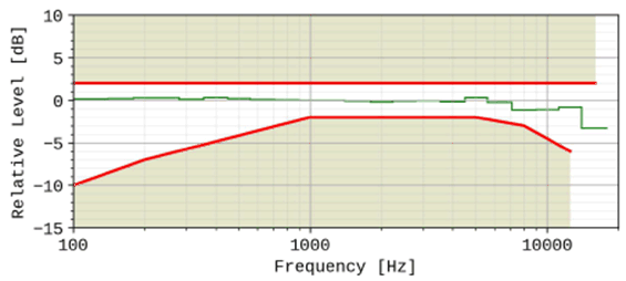
The receiving sensitivity frequency response measured at the electrical reference point shall be within a mask, which can be drawn with straight lines between the breaking points in Table 30a2 on a logarithmic (frequency) - linear (dB sensitivity) scale.
| Frequency (Hz) | Upper limit (dB) | Lower limit (dB) |
|---|---|---|
| 100 | 2 | -10 |
| 200 | 2 | -7 |
| 1000 | 2 | -2 |
| 3000 | 2 | -2 |
| 5000 | 2 | -2 |
| 8000 | 2 | -3 |
| 12500 | 2 | -6 |
| 16000 | 2 | |
|
NOTE:
All sensitivity values are expressed in dB on an arbitrary scale.
|
||

Figure 16b: Electrical interface sensitivity/frequency masks. The frequency response of the EVS codec operating as specified in TS 26.132 (super-wideband 24,4kbit/s, using the specified P.501 speech test signal), is plotted for reference, normalized to 0dB at 1kHz.
(⇒ copy of original 3GPP image)
(⇒ copy of original 3GPP image)
A UE operating in super-wideband mode shall pass the super-wideband requirements (i.e. when measured according to in 1/3rd octaves) as specified in Table 30a2, and shall also pass the wideband sensitivity/frequency characteristics requirements in the wideband range using the wideband measurement (i.e. measured in 1/12th octaves) as specified in Table 14a2.
Compliance shall be checked by the relevant test described in TS 26.132.