Content for TS 23.304 Word version: 19.0.0
1…
4…
4.2.3…
4.2.7…
4.3…
5…
5.1.4…
5.1.5…
5.2…
5.3…
5.4…
5.5…
5.6…
5.7
5.8…
5.9…
6…
6.1.2…
6.2…
6.3…
6.3.2…
6.3.2.3…
6.3.2.4…
6.4…
6.4.3…
6.5…
6.5.2…
6.6…
6.7…
6.7.2…
6.8…
7…
7.2…
6.7 5G ProSe UE-to-UE Relay Communication
6.7.1 5G ProSe Communication via 5G ProSe Layer-3 UE-to-UE Relay
6.7.1.1 Layer-2 link establishment for PC5 communication via 5G ProSe Layer-3 UE-to-UE Relay
6.7.1.2 Link identifier update for PC5 communication via 5G ProSe Layer-3 UE-to-UE Relay
6.7.1.3 Layer-2 link release for PC5 communication via 5G ProSe Layer-3 UE-to-UE Relay
6.7.1.4 Layer-2 link modification for PC5 communication via 5G ProSe Layer-3 UE-to-UE Relay
6.7.1.5 Layer-2 link maintenance for PC5 communication via 5G ProSe Layer-3 UE-to-UE Relay
...
...
6.7 5G ProSe UE-to-UE Relay Communication |R18| p. 123
6.7.1 5G ProSe Communication via 5G ProSe Layer-3 UE-to-UE Relay p. 123
6.7.1.1 Layer-2 link establishment for PC5 communication via 5G ProSe Layer-3 UE-to-UE Relay p. 123
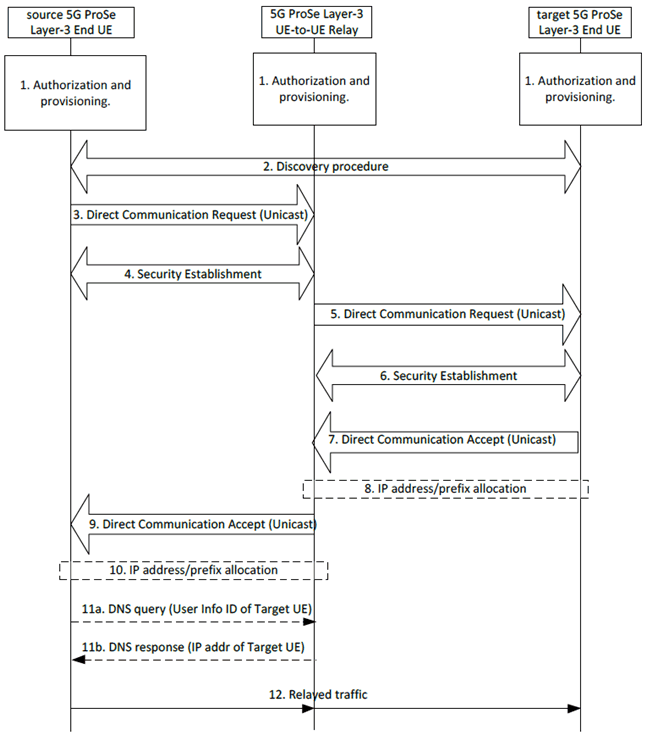
Figure 6.7.1.1-1 shows the procedure for Layer-2 link establishment via 5G ProSe Layer-3 UE-to-UE Relay.

Figure 6.7.1.1-1: Layer-2 link establishment via 5G ProSe Layer-3 UE-to-UE Relay
(⇒ copy of original 3GPP image)
(⇒ copy of original 3GPP image)
Step 1.
In the case of one source 5G ProSe Layer-3 End UE communicates with multiple target 5G ProSe Layer-3 End UEs, the PC5 link between the source 5G ProSe Layer-3 End UE and the 5G ProSe Layer-3 UE-to-UE Relay can be shared for multiple target 5G ProSe Layer-3 End UEs per RSC while the PC5 links may be established individually between the 5G ProSe Layer-3 UE-to-UE Relay and target 5G ProSe Layer-3 End UEs per RSC. For the shared PC5 link, the Layer-2 link modification procedure shall be used, replacing the step 3 to 4 and 9 to 10 of the procedure in Figure 6.7.1.1-1. The parameters used in the Layer-2 link modification procedure are described in clause 6.4.3.7.
In the case of multiple source 5G ProSe Layer-3 End UEs communicate with one target 5G ProSe Layer-3 End UE, the PC5 link between the 5G ProSe Layer-3 UE-to-UE Relay and the target 5G ProSe Layer-3 End UE can be shared per RSC while the PC5 links may be established individually between the source 5G ProSe Layer-3 End UEs and the 5G ProSe Layer-3 UE-to-UE Relay per RSC. For the shared PC5 link, the Layer-2 link modification procedure shall be used, replacing the step 5 to 8 of the procedure in Figure 6.7.1.1-1. The parameters used in the Layer-2 link modification procedure are described in clause 6.4.3.7.
Service authorization and provisioning are performed for source 5G ProSe Layer-3 End UE, target 5G ProSe Layer-3 End UE and 5G ProSe Layer-3 UE-to-UE Relay as described in clause 6.2.
Step 2.
The source 5G ProSe Layer-3 End UE performs discovery of a 5G ProSe Layer-3 UE-to-UE Relay as described in clause 6.3.2.4.
Step 3.
The source 5G ProSe Layer-3 End UE sends a Direct Communication Request message to initiate the unicast Layer-2 link establishment procedure with the 5G ProSe Layer-3 UE-to-UE Relay. The parameters included in the Direct Communication Request message are described in clause 6.4.3.7.
The Source Layer-2 ID of the Direct Communication Request message is self-assigned by the source 5G ProSe Layer-3 End UE and the Destination Layer-2 ID is set to the Source Layer-2 ID of the discovery message of the 5G ProSe Layer-3 UE-to-UE Relay.
The source 5G ProSe Layer-3 End UE gets application information and optional ProSe Application Requirements from ProSe application layer, and determines the end-to-end QoS parameters as described in clause 5.6.3.1.
Step 4.
IIf the User Info ID of 5G ProSe Layer-3 UE-to-UE Relay in the Direct Communication Request message matches the 5G ProSe UE-to-UE Relay's User Info ID and the RSC in the Direct Communication Request matches one RSC that the relay is (pre)configured with, as specified in clause 5.1.5.1, the 5G ProSe Layer-3 UE-to-UE Relay responds by establishing the security with the source 5G ProSe Layer-3 End UE. When the security protection is enabled, the source 5G ProSe Layer-3 End UE sends the parameters as described in clause 6.4.3.7 to the 5G ProSe Layer-3 UE-to-UE Relay.
If the Ethernet MAC address of source 5G ProSe Layer-3 End UE is already used by another 5G ProSe Layer-3 End UE, then the 5G ProSe Layer-3 UE-to-UE Relay rejects the direct link establishment indicating that the MAC address is not unique.
The Source Layer-2 ID used for the security establishment procedure is self-assigned by the 5G ProSe Layer-3 UE-to-UE Relay and the Destination Layer-2 ID is set to the Source Layer-2 ID of the received Direct Communication Request message.
The 5G ProSe Layer-3 UE-to-UE Relay shall choose different Source Layer-2 IDs for PC5 links of different types of traffic, i.e., IP traffic, Ethernet traffic and Unstructured traffic.
If the PC5 link is used for transferring Unstructured traffic, the 5G ProSe Layer-3 UE-to-UE Relay shall choose different Source Layer-2 IDs for different pair of source and target 5G ProSe Layer-3 End UEs.
Upon receiving the security establishment procedure messages, the source 5G ProSe Layer-3 End UE obtains the 5G ProSe Layer-3 UE-to-UE Relay's Layer-2 ID for future communication, for signalling and data traffic for this unicast link.
Step 5.
After the Security Establishment procedure in step 4 is completed, the 5G ProSe Layer-3 UE-to-UE Relay decides whether to use an existing unicast Layer-2 link between itself and the target 5G ProSe End UE for the required service. If there is no existing unicast Layer-2 link of the required RSC with the target 5G ProSe Layer-3 End UE, the 5G ProSe Layer-3 UE-to-UE Relay sends a Direct Communication Request message to initiate the unicast Layer-2 link establishment procedure with the target 5G ProSe Layer-3 End UE. The parameters included in the Direct Communication Request message are described in clause 6.4.3.7.
The Source Layer-2 ID of the Direct Communication Request message is self-assigned by the 5G ProSe Layer-3 UE-to-UE Relay and the Destination Layer-2 ID may be broadcast or unicast Layer-2 ID. Unicast Layer-2 ID is used only if the Layer-2 ID of the target 5G ProSe Layer-3 End UE associated with the user info (i.e. Application Layer ID) is known to the 5G ProSe Layer-3 UE-to-UE Relay.
The 5G ProSe Layer-3 UE-to-UE Relay shall choose different Source Layer-2 IDs for PC5 links of different types of traffic, i.e., IP traffic, Ethernet traffic and Unstructured traffic.
If the PC5 link is used for transferring Unstructured traffic, the 5G ProSe Layer-3 UE-to-UE Relay shall choose different Source Layer-2 IDs for different pair of source and target 5G ProSe Layer-3 End UEs.
Step 6.
If the RSC included in the Direct Communication Request matches the target UE's RSC that the target UE is (pre)configured with as specified in clause 5.1.5.1 and if the user info included in the Direct Communication Request matches the target UE's user info, the target 5G ProSe Layer-3 End UE responds by establishing the security with the 5G ProSe Layer-3 UE-to-UE Relay. When the security protection is enabled, the 5G ProSe Layer-3 UE-to-UE Relay sends the parameters as described in clause 6.4.3.7 to the target 5G ProSe Layer-3 End UE.
The Source Layer-2 ID used for the security establishment procedure is self-assigned by the target 5G ProSe Layer-3 End UE and the Destination Layer-2 ID is set to the Source Layer-2 ID of the received Direct Communication Request message.
Upon receiving the security establishment procedure messages, the 5G ProSe Layer-3 UE-to-UE Relay obtains the target 5G ProSe Layer-3 End UE's Layer-2 ID for future communication, for signalling and data traffic for this unicast link.
Step 7.
The target 5G ProSe Layer-3 End UE sends a Direct Communication Accept message to the 5G ProSe Layer-3 UE-to-UE Relay that has successfully established security with. The parameters included in the Direct Communication Accept message are described in clause 6.4.3.7.
Step 8.
For IP traffic, IPv6 prefix or IPv4 address is allocated for the target 5G ProSe Layer-3 End UE as defined in clause 5.5.1.4.
Step 9.
After receiving the Direct Communication Accept message from the target 5G ProSe Layer-3 End UE, the 5G ProSe Layer-3 UE-to-UE Relay sends a Direct Communication Accept message to the source 5G ProSe Layer-3 End UE that has successfully established security with. The parameters included in the Direct Communication Accept message are described in clause 6.4.3.7.
Step 10.
For IP traffic, IPv6 prefix or IPv4 address is allocated for the source 5G ProSe Layer-3 End UE as defined in clause 5.5.1.4.
Step 11.
For IP communication, the 5G ProSe Layer-3 UE-to-UE Relay may store an association of user info (i.e. Application Layer ID) and the IP address of target 5G ProSe Layer-3 End UE into its DNS entries and the 5G ProSe Layer-3 UE-to-UE Relay may act as a DNS server to other UEs. The source 5G ProSe Layer-3 End UE may send a DNS query to the 5G ProSe Layer-3 UE-to-UE Relay to request IP address of target 5G ProSe Layer-3 End UE after step 10 if the IP address of target 5G ProSe Layer-3 End UE is not received in step 9 and the 5G ProSe Layer-3 UE-to-UE Relay returns the IP address of the target 5G ProSe Layer-3 End UE to the source 5G ProSe Layer-3 End UE.
For Ethernet communication, the 5G ProSe Layer-3 UE-to-UE Relay maintains the association between PC5 links and Ethernet MAC addresses received from the 5G ProSe Layer-3 End UE.
For Unstructured traffic communication, for each pair of source and target 5G ProSe Layer-3 End UEs, the 5G ProSe Layer-3 UE-to-UE Relay maintains the 1:1 mapping between the PC5 link with source 5G ProSe Layer-3 End UE and the PC5 link with target 5G ProSe Layer-3 End UE.
Step 12.
The source 5G ProSe Layer-3 End UE communicates with the target 5G ProSe Layer-3 End UE via the 5G ProSe Layer-3 UE-to-UE Relay.
6.7.1.2 Link identifier update for PC5 communication via 5G ProSe Layer-3 UE-to-UE Relay p. 126
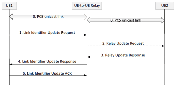
The Link Identifier Update procedure as defined in clause 6.4.3.2 is reused between source 5G ProSe Layer-3 End UE and 5G ProSe Layer -3 UE-to-UE Relay to perform a link identifier update. When the IP address/prefix is changed, the new one is shared between source 5G ProSe Layer-3 End UE and target 5G ProSe Layer-3 End UE as depicted in Figure 6.7.1.2-1.

Figure 6.7.1.2-1: Link Identifier Update and IP address/prefix sharing via 5G ProSe Layer-3 UE-to-UE Relay
(⇒ copy of original 3GPP image)
(⇒ copy of original 3GPP image)
Step 0.
A PC5 link is established between a source 5G ProSe Layer-3 End UE (i.e. UE1) and a 5G ProSe Layer-3 UE-to-UE Relay (i.e. UE-to-UE Relay). Another PC5 link is established between the UE-to-UE Relay and the target 5G ProSe Layer-3 End UE (i.e. UE2). IP data may be exchanged between UE1 and UE2 via the UE-to-UE Relay over the PC5 links. During the link establishment, UE1 informs the UE-to-UE Relay that the link requires privacy.
Step 1.
As stated in clause 6.4.3.2, according to the privacy requirement, UE1 may trigger link identifier update procedure. UE1 sends a Link Identifier Update Request message to the UE-to-UE Relay including the following parameters:
Step 2.
- its new Layer-2 ID, new security information, new Application layer ID (if provided by the upper layer).
- If UE1's IP address/prefix needs to be changed:
- if UE 1's IP address/prefix is allocated by the UE-to-UE Relay, UE1 includes "new IP address needed" indication.
- if UE1 self-assign its IP address/prefix, UE1 includes its new IP address/prefix.
- its peer UEs information (e.g. UE2's IP address, UE2's Application layer ID), allowing the UE-to-UE Relay to inform UE1's peer UEs (e.g. UE2) about UE1's new allocated IP address/prefix.
UE-to-UE Relay self-assigns a new L2 ID, new security information and possibly new IP address/prefix for PC5 link with UE1.
Step 3.
- If a "new IP address needed" indication is received, UE-to-UE Relay assigns a new IP address/prefix to UE1 and saves it locally.
UE2 receives the PC5 Relay Update Request message and saves UE1's new IP address/prefix. UE2 sends a PC5 Relay Update Response message to the UE-to-UE Relay including all parameters received on the PC5 Relay Update Request message.
UE2 continues to receive IP data with UE1's old IP address (transit packets sent prior to UE1's receiving its new IP address) until an IP packet using UE1's new IP address is received. At this point, UE2 starts using UE1's new IP address and may forget UE1's old IP address.
Step 4.
UE-to-UE Relay sends a Link Identifier Update Response message to UE1 including UE1's new IP address/prefix, UE-to-UE Relay's new Layer-2 ID, new security information and possibly new IP address/prefix and/or new Application layer ID.
Step 5.
UE1 saves its new IP address/prefix and UE-to-UE Relay's new parameters and sends a Link Identifier Update ACK message to the UE-to-UE Relay, including its new IP address received on the Link Identifier Update Response message. UE1 and UE-to-UE Relay start using the new Layer-2 IDs and new security information for PC5 communication. UE1 starts using its new IP address for IP data exchange with UE2.
6.7.1.3 Layer-2 link release for PC5 communication via 5G ProSe Layer-3 UE-to-UE Relay p. 128
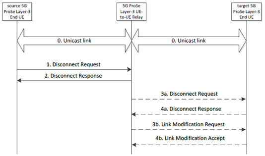
Figure 6.7.1.3-1 shows the Layer-2 link release procedure via 5G ProSe Layer-3 UE-to-UE Relay.

Figure 6.7.1.3-1: Layer-2 Link Release procedure via 5G ProSe Layer-3 UE-to-UE Relay
(⇒ copy of original 3GPP image)
(⇒ copy of original 3GPP image)
Step 0.
The source 5G ProSe Layer-3 End UE and the 5G ProSe Layer-3 UE-to-UE Relay and the 5G ProSe Layer-3 UE-to-UE Relay and the target 5G ProSe Layer-3 End UE have a unicast link established as described in clause 6.7.1.1.
Step 1.
The source 5G ProSe Layer-3 End UE sends a Disconnect Request message to the 5G ProSe Layer-3 UE-to-UE Relay in order to release the layer-2 link and deletes all context data associated with the layer-2 link.
Step 2.
Upon reception of the Disconnect Request message, the 5G ProSe Layer-3 UE-to-UE Relay shall respond with a Disconnect Response and deletes all context data associated with the layer-2 link.
Step 3a.
Upon reception of the Disconnect Request message, the 5G ProSe Layer-3 UE-to-UE Relay sends a Disconnect Request message to the target 5G ProSe Layer-3 End UE(s), which has a unicast link for the communication with the source 5G ProSe Layer-3 End UE if there are no other UEs using the layer-2 link.
Step 4a.
Upon reception of the Disconnect Request message, the target 5G ProSe Layer-3 End UE shall respond with a Disconnect Response message.
Step 3b.
Upon reception of the Disconnect Request message, the 5G ProSe Layer-3 UE-to-UE Relay sends a Link Modification Request message to the target 5G ProSe Layer-3 End UE(s), which has a unicast link for the communication with the source 5G ProSe Layer-3 End UE if there are other UEs using the layer-2 link in order to release the PC5 QoS Flow(s) and deletes the context data associated with the PC5 QoS Flow(s).
Step 4b.
Upon reception of the Link Modification Request message, the target 5G ProSe Layer-3 End UE shall respond with a Link Modification Accept message and deletes the context data associated with the PC5 QoS Flow(s) used for the communication with the source 5G ProSe Layer-3 End UE.
The ProSe layer of the 5G ProSe Layer-3 UE-to-UE Relay and the target 5G ProSe Layer-3 End UE provides information about the unicast link modification to the AS layer, which enables the AS layer to update the context related to the modified unicast link.
6.7.1.4 Layer-2 link modification for PC5 communication via 5G ProSe Layer-3 UE-to-UE Relay p. 129
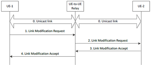
Figure 6.7.1.4-1 shows the Layer-2 link modification procedure via Layer-3 UE-to-UE Relay. This procedure is used to add/modify/remove PC5 QoS Flow(s) in the existing PC5 unicast link as described in clause 6.4.3.7.3.

Figure 6.7.1.4-1: Layer-2 link modification procedure via Layer-3 UE-to-UE Relay
(⇒ copy of original 3GPP image)
(⇒ copy of original 3GPP image)
Step 0.
UE-1 and UE-to-UE Relay and UE-to-UE Relay and UE-2 have a unicast link established as described in clause 6.7.1.1.
Step 1.
UE-1 sends a Link Modification Request to UE-to-UE Relay as described in clause 6.4.3.7.3.
Step 2.
Upon reception of the Link Modification Request message from UE-1, the UE-to-UE Relay sends a Link Modification Request to UE-2 as described in clause 6.4.3.7.3.
Step 3.
UE-2 responds with a Link Modification Accept message to the UE-to-UE Relay as described in clause 6.4.3.7.3.
Step 4.
Upon reception of the Link Modification Accept message from UE-2, the UE-to-UE Relay responds with a Link Modification Accept message to the UE-1 as described in clause 6.4.3.7.3.
6.7.1.5 Layer-2 link maintenance for PC5 communication via 5G ProSe Layer-3 UE-to-UE Relay p. 129
The Layer-2 link maintenance over the PC5 reference point procedure as described in clause 6.4.3.5 can be used for the Layer-2 link established between the source 5G ProSe Layer-3 End UE and the 5G ProSe Layer-3 UE-to-UE Relay and between the 5G ProSe Layer-3 UE-to-UE Relay and the target 5G ProSe Layer-3 End UE.