Content for TS 23.255 Word version: 19.0.0
7.6 Change of USS during flight
7.6.1 General
7.6.2 Procedures
7.6.2.1 Management of multi-USS configuration
7.6.2.2 Multi-USS configuration
7.6.2.3 UAE layer assisted change of USS
7.6.2.4 UAE client assisted change of USS
7.6.2.5 UAE server triggered change of USS
7.6.3 Information flows
7.6.3.1 Multi-USS management request
7.6.3.2 Multi-USS management response
7.6.3.3 Multi-USS management complete
7.6.3.4 Multi-USS configuration request
7.6.3.5 Multi-USS configuration response
7.6.3.6 USS change request
7.6.3.7 USS change response
7.6.3.8 USS change notification
7.6.3.9 USS change trigger notify
...
...
7.6 Change of USS during flight |R18| p. 49
7.6.1 General p. 49
This feature introduces the UAS application enablement services for supporting change of UAS application specific server. In particular, the UAE layer provides support for the following operations:
- Support of the registration of the UAE clients multi-USS capability to the UAE server as described in clause 7.1a.
- Support the distribution of the for multi-USS policies from the UAS application specific server to the UAE server and the UAE client, as described in clause 7.6.2.1 and clause 7.6.2.2.
- Support the change of UAS application specific server, as described in clause 7.6.2.3.
- Support the UAE server triggered change of USS, as described in clause 7.6.2.5.
7.6.2 Procedures p. 50
7.6.2.1 Management of multi-USS configuration p. 50
This procedure manages the multi-USS policies at the UAE server, based on an application request from UAS application specific server to support the change of USS for a UAS.
Figure 7.6.2.1-1 illustrates the procedure where the UAE server receives an application request for managing the multi-USS policies for a UAS from the UAS application specific server.
Pre-condition:
- The UAV has received its UAS ID from the UAS application specific server.
- The UAV has performed the UAS UE registration procedure.
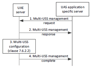
Step 1.
The UAS application specific server sends to the UAE server a Multi-USS management request. The request includes the UAV (UAE client) identifier and the Multi-USS policies. A Multi-USS policy contains: allowed target USSes (identified by e.g. FQDN), serving USS information, and additional information for change of USS (USS change constraints parameter geo location/area threshold for change of USS by UAV). The UAE server stores the Multi-USS policies corresponding to the UAV ID. In case of removal of a Multi-USS policy for a USS from the UAE server, the request shall include the UAV identifier and a USS identifier (e.g. FQDN) for the USS that will be removed.
Step 2.
The UAE server sends to the UAS application specific server a Multi-USS management response with a positive or negative acknowledgement of the request.
Step 3.
UAE server executes the multi-USS configuration according to clause 7.6.2.2.
Step 4.
After execution of USS management configuration, the UAE server notifies the UAS application specific server with a Multi-USS management complete based on the configured capabilities of the UAE client.
7.6.2.2 Multi-USS configuration p. 50
This procedure enables the configuration of the UAE client, based on a request from UAS application specific server to configure multi-USS policies to the UAE client.
Figure 7.6.2.2-1 illustrates the Multi-USS configuration procedure.
Pre-conditions:
- The UAS UEs are connected to 5GS and authenticated and authorized by UAS application specific server as specified in clause 5.2 of TS 23.256.
- UAE server has established a UAE session with the respective UAE clients as the UAE clients are successfully registered to the UAE server.
- UAE server has performed the Multi-USS management procedure according to clause 7.6.2.1.
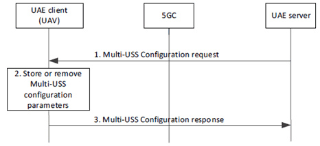
Step 1.
The UAE server sends a Multi-USS configuration request to the UAE client. The UAE client receives a Multi-USS configuration request that includes the Multi-USS policies from the UAE server. In case of removal of one or more Multi-USS policies for a USS from the UAE client, then the request shall only include a USS identifier (e.g. FQDN) for the USSes that will be removed.
Step 2.
The UAE client stores or removes the Multi-USS policies as per the information received in step 1.
Step 3.
The UAE client sends a Multi-USS configuration response to the UAE server.
7.6.2.3 UAE layer assisted change of USS p. 51
This procedure provides a mechanism for supporting dynamic change of USS which may be performed while the UAV flight is ongoing, due to expected location/mobility of the UAV, emergency events, etc.
Figure 7.6.2.3-1 illustrates the procedure where the UAE server supports the change of USS.
Pre-conditions:
- UAE client has indicated support of change of USS by the Multi-USS capability.
- UAS application specific server has provided Multi-USS policies to the UAE client and the UAE server.
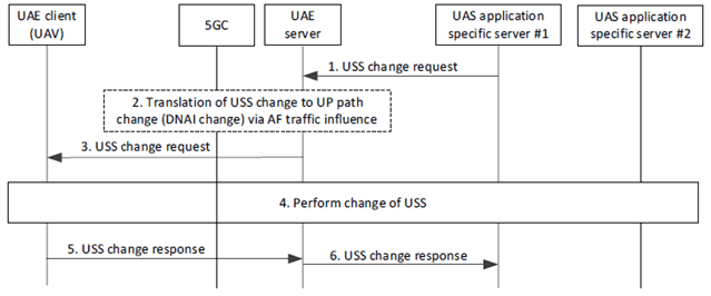
Step 1.
The UAE server receives a USS change request from a serving USS (UAS application specific server #1), indicating that a target USS (UAS application specific server #2) an take over the communication. The request includes the UAV (UAE client) identification information, target USS information and USS change authorization information (e.g. authorization token). Optionally, updated Multi-USS policies for one or more USSes can be included. The UAE server verifies that the request is authorized (e.g., Multi-USS capability is enabled, new USS part of the allowed USS information).
Step 2.
If required, the UAE server translates this to a UP path change and interacts with NEF as AF for influence UP path (switching to target DNAI). In particular UAE server (acting as AF) checks whether it can serve the target DNAI corresponding to the target USS based on the mapping of USS to DNAI which was performed in step 2 of clause 7.6.2.5. Interaction with 5GC is performed according to functionality for application function influence on traffic routing, see clause 4.3.6.3 of TS 23.502.
Step 3.
The UAE server forwards the USS change request to the UAE client including target USS information and updated Multi-USS policies.
Step 4.
Perform change of USS.
The UAE client initiates communication with the target USS based on the USS change request and the Multi-USS policies.
Step 5.
The UAE client sends a USS change response indicating to what USS the change of USS has been performed.
Step 6.
The UAE server sends a USS change response to the UAS application specific server indicating that a change of USS has been performed.
7.6.2.4 UAE client assisted change of USS p. 52
This procedure enables the UAE client to provide a dynamic change of USS while the UAV flight is ongoing, due to an emergency change of USS deemed necessary by the UAE client. The UAE client initiates the change of USS on behalf of the USS based on previously provided Multi-USS policy.
Figure 7.6.2.4-1 illustrates the procedure where the UAE server supports the change of USS.
Pre-conditions:
- UAE client has indicated support of change of USS by the Multi-USS capability.
- UAS application specific server has provided Multi-USS policies to the UAE client and the UAE server.
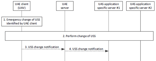
Step 1.
An emergency change of USS is deemed necessary by the UAE Client, and the UAE client initiates the change of USS on behalf of the USS based on previously provided Multi-USS policy.
Step 2.
Perform change of USS. The UAE client initiates communication with the target USS (UAS application specific server #2) based on the previously provided Multi-USS policies.
Step 3.
The UAE client sends a USS change notification indicating to what USS the change of USS has been performed. The identity of the target USS (UAS application specific server #2) is included. The USS change notification is only sent if the UAE client has a connection to the UAE server.
Step 4.
The UAE server sends a USS change notification to the UAS application specific server #1 indicating that a change of USS has been performed.
7.6.2.5 UAE server triggered change of USS p. 53
In multi-USS scenarios, each USS can be physically located in different clouds, and it is also possible that a USS is deployed at the edge.
Figure 7.6.2.5-1 illustrates the procedure where the UAE server supports change of USS for a multi-USS/LUN scenario, where the interaction with the communication network for supporting a UAS session requires the interaction to more than one USS e.g., due to UAV mobility to different geographical area covered by different edge clouds.
Pre-conditions:
- The UAV has performed the UAS UE registration procedure.
- UAE client and UAE server have indicated multi-USS support.
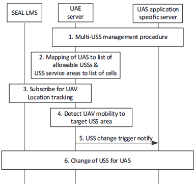
Step 1.
The UAE server has performed the USS management procedure of clause 7.6.3.1; however, at the multi-USS management request, UAE server also receives from UAS application specific server the USS service areas (geographical) for all allowed USSs, and optionally the USS to DNAI mapping and a USS list per given Local USS network (LUN).
Step 2.
The UAE server maps each USS with different topological areas based on the USS to DNAI mapping (based on step 1), for all USSs which are allowed for a target area where the UAV is allowed to fly (e.g. within the LUN). Then it also maps and stores all pairs of <USS x, DNAI y> per LUN or for the areas of interest for the UAV (e.g., based on the allowable routes).
Step 3.
The UAE server tracks the location of the UAV, by requesting on-demand location monitoring from SEAL LMS (acting as VAL server in procedure of clause 9.3.4 or clause 9.3.5 of TS 23.434) or via subscribing for monitoring the UAV location deviation (specified in clause 9.3.11 of TS 23.434).
Step 4.
The UAE server detects an expected UAV location change to an area covered by a different USS (based on SEAL LMS monitoring subscription/request as in step 3), it generates a trigger event indicating that the UE moves to an area where the USS is overlapping with other USS, or another overlapping USS within LUN area is not available.
If it is an overlap, the UAE server checks whether the performance of serving USS is expected to get impacted (e.g., by requesting DN performance analytics for the target area) or if the serving USS is not supported at target area, checks what is the best available USS and whether this can provide the same services. The criteria for the best available USS may relate to the location of the UAV, but it can also be the priorities of the USS (based on the policies received) at the target area and the capabilities (services) provided by the target USS.
Step 5.
The UAE server sends to the UAS application specific server a USS change trigger notify indicating the recommendation for a USS change for the UAS and provides the target USS ID. Alternatively, the trigger message indicates a UAV mobility event, based on steps 3/4.
Step 6.
The UAS change procedure follows as specified in clause 7.6.2.3.
7.6.3 Information flows p. 54
7.6.3.1 Multi-USS management request p. 54
Table 7.6.3.1-1 describes the information flow Multi-USS management request from the UAS application specific server to the UAE server.
| Information element | Status | Description |
|---|---|---|
| UASS ID | M | Identity of the UAS application specific server which requests the Multi-USS management. This ID can be the USS identifier, when the UAS application specific server is the USS. |
| UAS ID | M | The identification of the UAS for which the Multi-USS management request applies. This could be in form of identifier for the UAS, e.g group ID; or collection of individual identifiers for the UAV and UAV-C, e.g. CAA level UAV ID, GPSI |
| UAS registration area | O | The registration area where the UAV is allowed to fly |
| UAS allowed route | O | The UAV allowed route within the registration area. |
| Multi-USS policy management container (see NOTE) | O | The Multi-USS policy management container consists of the requirements and policy for Multi-USS management. |
| > Serving USS information | M | Information about the serving USS identifier |
| > Additional information for change of USS | M | Information about the serving USS, related with the switch to a particular target USS |
| > Area for change of USS | M | The area where the Multi-USS management request applies. This can be geographical area, or topological area in which the capability is active. |
| > Allowed USS(s) information | O | The information for the allowed USSs for the UAS. |
| >> USS ID | M | The identity of the allowed USS from the list of USSs for the target UAS (identified e.g. by FQDN) |
| >> USS service area | M | The geographical area per USS |
| >> USS service requirements | M | The capabilities and key performance requirements per each USS service. |
| >> List of USS DNAI(s) | M | DNAI(s) associated with the target USS. |
| >> LUN ID | M | Identity of the LUN where the report applies |
|
NOTE:
If Multi-USS policy management container is not included for a USS, it indicates removal of the Multi-USS policy management related information for this USS.
|
||
7.6.3.2 Multi-USS management response p. 54
Table 7.6.3.2-1 describes the information flow Multi-USS management response from the UAE server to the UAS application specific server.
| Information element | Status | Description |
|---|---|---|
| Result | M | The positive or negative result of the Multi-USS management request. |
7.6.3.3 Multi-USS management complete p. 55
Table 7.6.3.3-1 describes the information flow Multi-USS management complete from the UAE server to the UAS application specific server.
| Information element | Status | Description |
|---|---|---|
| Result | M | The positive or negative result of the Multi-USS configuration. |
7.6.3.4 Multi-USS configuration request p. 55
Table 7.6.3.4-1 describes the information flow Multi-USS configuration request from the UAE server to the UAE client.
| Information element | Status | Description |
|---|---|---|
| UAS ID | M | The identification of the UAS for which the Multi-USS configuration request applies. This could be in form of identifier for the UAS, e.g. group ID; or collection of individual identifiers for the UAV and UAV-C, e.g. CAA level UAV ID, GPSI. |
| Multi-USS policy management configuration (see NOTE) | O | The Multi-USS policy management configuration information to be configured at the UAS. |
| > Allowed USS | M | Identifier of a USS that can be the target of a switch (identified e.g. by FQDN) |
| > Serving USS information | M | Information about the serving USS identifier |
| > Additional information for change of USS | M | Information about the serving USS, related with the switch to a particular target USS |
| > Area for change of USS | M | The area where the Multi-USS management request applies. This can be geographical area, or topological area in which the capability is active. |
|
NOTE:
If Multi-USS policy management configuration is not included for a USS, it indicates removal of the Multi-USS policy management configuration for this USS.
|
||
7.6.3.5 Multi-USS configuration response p. 55
Table 7.6.3.5-1 describes the information flow Multi-USS configuration response from the UAE client to the UAE server.
| Information element | Status | Description |
|---|---|---|
| Result | M | The positive or negative result of the Multi-USS configuration |
7.6.3.6 USS change request p. 55
Table 7.6.3.6-1 describes the information flow USS change request from the UAS application specific server to the UAE server and from the UAE server to the UAE client.
| Information element | Status | Description |
|---|---|---|
| UASS ID | M | Identity of the UAS application specific server which requests the change of USS. This ID can be the USS identifier, when the UAS application specific server is the USS. |
| UAS ID | M | The identification of the UAS for which the USS change request applies. This could be in form of identifier for the UAS, e.g. group ID; or collection of individual identifiers for the UAV and UAV-C, e.g. CAA level UAV ID, GPSI. |
| USS change authorization information | M | An authorization token to verify the request. |
| Target USS | M | Identification of the USS that is the target of a switch (identified e.g. by FQDN) |
| Target USS info | M | Information for the target USS |
| > USS endpoint | M | Endpoint information (e.g. URI, FQDN, IP address) used to communicate with the USS. |
| > USS capabilities | O | The capabilities supported by the target USS |
| > LUN ID | O | Identity of the LUN where the serving/target USS belongs |
| >List of USS DNAI(s) | O | DNAI(s) associated with the target USS. |
7.6.3.7 USS change response p. 56
Table 7.6.3.7-1 describes the information flow USS change response/notification from the UAE client to the UAE server and from the UAE server to the UAS application specific server.
| Information element | Status | Description |
|---|---|---|
| Result | M | The positive or negative result of the USS change request. |
7.6.3.8 USS change notification p. 56
Table 7.6.3.8-1 describes the information flow USS change notification from the UAE client to the UAE server and from the UAE server to the UAS application specific server.
| Information element | Status | Description |
|---|---|---|
| Reason | M | Reason for change of /USS. |
| Target USS information | M | Identifier of the new USS that the UAV has connected to (identified e.g. by FQDN). |
7.6.3.9 USS change trigger notify p. 56
Table 7.6.3.9-1 describes the information flow USS change trigger notify from the UAE server to the UAS application specific server.
| Information element | Status | Description |
|---|---|---|
| UAS ID | M | Identity of the UAS for which the trigger applies. |
| Serving USS ID | M | Identity of the serving USS. |
| Target USS ID | O | Identity of the target USS based on the recommendation. |
| LUN ID | O | Identity of the LUN where the serving USS belongs. |
| UAV mobility event | O | The mobility event e.g., expected UE mobility to a service area outside the current USS serving area. |