Content for TR 22.878 Word version: 18.2.0
4.1.3 Timing Resiliency p. 9
A simple overview of a power sub-station is provided in Figure 4.1.3-1. In a typical deployment today, the sub-station achieves time synchronization by means of a grandmaster clock that uses the IEEE 1588 Precision Time Protocol (PTP) [4] protocol to synchronize elements inside the power sub-station via an Ethernet connection. The grandmaster clock often uses a GNSS receiver to achieve time synchronization information. To access the GNSS signal, an external GNSS antenna is typically required. The Figure shows how time and communication redundancy can be achieved within substation by means defined in IEC 61850-9-3-2016 [3]. However, since the time source (GNSS) illustrated is a single point of failure (e.g. whenever satellite(s) are not available or there is interference), 5G is a candidate resiliency solution.
![Copy of original 3GPP image for 3GPP TS 22.878, Fig. 4.1.3-1: Example power sub-system setup leveraging 2x GNSS based clock grandmasters [5]](../img/tinv-22-878-4.1.3-1.gif)
Figure 4.1.3-1: Example power sub-system setup leveraging 2x GNSS based clock grandmasters [5]
(⇒ copy of original 3GPP image)
(⇒ copy of original 3GPP image)
The GNSS receiver elements of the clock grandmaster installed in power-subsystems have some desirable characteristics including intrinsic multi-layer jamming and spoofing detection capabilities, e.g., autonomous disruption detection and intelligent protection and control. The timing accuracy requirement of the GNSS receiver is <250 ns according to the grandmaster requirements listed in [4]. This allows sufficient budget for synchronization distribution errors within the power sub-station versus the E2E requirements of the Smart Grid operation (e.g., where every PTP sync device needs to be synchronized to a <1 μs accuracy).
Many power sub-systems already have cellular 4G coverage. A 5G System-based timing solution offers multiple potential enhancements, including:
- As a resiliency solution to the GNSS received timing solution if GNSS fails or is compromised, e.g., integrated as alternative radio in each grandmaster clock or as an alternative grandmaster clock with 5G capability in the power sub-system.
- As an alternative to GNSS use, e.g., integrated with PTP grandmaster clock avoiding installation of external GNSS antenna and receiver at the power sub-station.
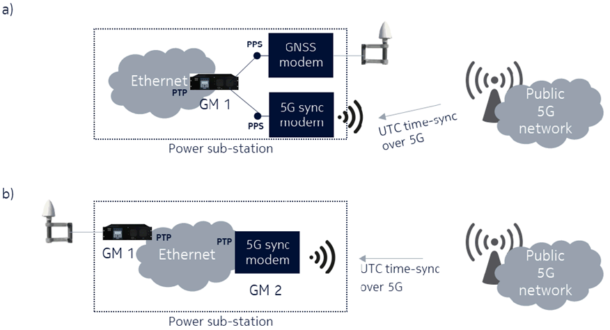
Figure 4.1.3-2: 5G integration into system - resilience and alternative mode
(⇒ copy of original 3GPP image)
(⇒ copy of original 3GPP image)
Another key requirement is holdover capability, the ability to continue providing accurate timing service in the event of loss of an external source (e.g., GNSS), for the 5G System. For option (a) in Figure 4.1.3-2 a 24 h holdover capability is automatically supported as this is the case for today's distributed solution where GM1 and GNSS is always one and the same device. 5G modem functionality could be either integrated into the same device as a chip or as an input using option (a) type external modem, e.g., for this case, no specific holdover capability is required from the 5G System. With option (b), holdover capability is mainly determined by the 5G network. Here it is desirable that the 5G sync modem has a holdover capability of at least 5 s to comply with [3] and that the 5G network can support up to 24 h of holdover capability. However, as option (a) can be a solution when 24 h holdover capability is strictly needed for the power utility, this requirement could be more scalable, e.g., allow for wider range of performance of 5G networks and 5G sync modems with exploiting also hold-over capability (stability) of GM1.
High level requirements to the 5G System to support these alternatives are highlighted in Table 4.1.3-1
| Area | Requirement |
|---|---|
| Time Domain | UTC, delivered from network to end-point device in power sub-station. An absolute time difference to GPS/GNSS is acceptable (can be preconfigured) as long as 5G end device provides PPS output which can be used for measuring the difference. |
| Deployment |
Wide area support is needed to reach power sub-systems, e.g., should support full coverage requirements. Mobility is low, e.g., power sub-systems are static structures.
Public Network [5]:
|
| Mobility | None, synchronization devices are static and vehicles connect to grid in a static location when in need of time synchronization. |
| Synchronization accuracy (examples) | <250-1000 ns for synchro phasor use-cases, e.g., to supplement/replace existing GNSS receiver based solutions 1:1. <1-10 μs for Power system protection and synchronization <1 ms for Event reporting use-cases, Disturbance recording use-cases |
| Holdover capability | Up to 24h for 5G network, e.g., the 5G network needs to maintain its ability to synchronize power sub-systems even after general loss or failure of UTC time source. >5 s for 5G sync modem [3] |
| Services provided by 5G System | Time resilience service provides 5G clock properties, e.g., clockClass, accuracy, etc to reflect the possible selection of clock source e.g., during GNSS unavailability. When acting as a backup or replacement time source, the 5G System provides secure timing service to UEs and application servers. |
![]()
![]()
![]()