Content for TS 23.221 Word version: 18.0.0
5 IP addressing
5.1 IP version issues
5.2 Interoperability between IPv4 and IPv6 networks
5.3 Address management
...
...
5 IP addressing p. 13
5.1 IP version issues p. 13
The EPS/UMTS/GSM architecture shall support IPv4 / IPv6 based on the statements below.
- IP transport between network elements of the IP Connectivity services (between RNC, SGSN, GGSN, eNodeB, MME, S-GW, and P-GW) and IP transport for the CS Domain: both IPv4 and IPv6 are options for IP Connectivity.
- For UEs used for Machine-Type Communications (MTC) IPv6 addressing as described in TS 23.401 and TS 23.060 should be the primary mechanism for IP addressing. IPv4 based addressing is considered a transition solution and is deprecated for MTC used over 3GPP accesses.
-
IM CN subsystem elements (UE to CSCF and the other elements e.g. MRF):
- The architecture should make optimum use of IPv6.
- 3GPP specifications design the IM CN subsystem elements and interfaces to support both IPv4 and IPv6. In the case the UE supports IPv4, the guidelines and recommendations in TR 23.981 should be followed.
- The UE may support IPv4 only, IPv6 only or both for the connection to the IM CN subsystem. In the case the UE supports IPv4, the guidelines and recommendations in TR 23.981 should be followed.
- According to the procedures defined in TS 23.060 and/or TS 23.401, when a UE is assigned an IPv6 prefix, it can change the global IPv6 address it is currently using via the mechanism defined in RFC 4941, or similar means.
- Access to existing data services (Intranet, Internet,…):
- The UE can access IPv4 and IPv6 based services.
5.2 Interoperability between IPv4 and IPv6 networks p. 13
Since the UE can access both IPv4 and IPv6 based services, situations may arise where interworking is needed to interoperate with IPv4 and IPv6 networks. This clause describes three different interworking scenarios: UE is IPv4 and IPv6 capable, IPv6 only UE, and IPv6 UE connected via IPv4 network to an IPv6 device. These scenarios are examples of IPv6 and IPv4 interworking. The scenarios presented below only considered cases of a Transition Gateway (TrGW) for generic services and specialist services may require additional functionally at the application level.
In addition to the following clauses, Annex B describes additional guidelines for interoperability if such function is required (e.g. IMS, MTC).
5.2.1 IPv4/IPv6 Mobile connecting to IPv4 and IPv6 networks p. 13
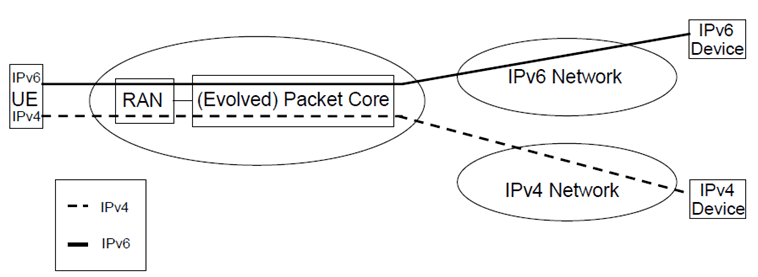
An installation where the UE has both IPv4 and IPv6 stacks is shown in Figure 5-1. As depicted, the terminal connects to the IPv4 device directly using an IPv4 PDP or EPS Bearer Context. Hence, the UE appears to be a standard IPv4 node to the external IPv4 network. This scenario does not need any specific transition support from the network. However, it requires both versions of IP at the UE. The GGSN/P-GW in this scenario may be different for the IPv6 and the IPv4 connections unless IPv4/v6 PDP or EPS Bearer Contexts are used. With GGSN/P-GW is meant either a GGSN or a P-GW.

Figure 5-1: UE with IPv4 and IPv6 capability connecting to IPv4 and IPv6 networks
(⇒ copy of original 3GPP image)
(⇒ copy of original 3GPP image)
5.2.2 IPv6 only Mobile connecting to IPv4 network p. 14

Figure 5-2 shows an IPv6 only terminal connected to an IPv4 device. The UE us using an IPv6 PDP or EPS Bearer Context for access to a Transition Gateway (TrGW) that translates the IPv6 packets to IPv4 and vice versa. The TrGW may be implemented as a Network Address Translation - Protocol Translation (NAT-PT) [16] to convert IPv6 traffic coming from the UE to IPv4 traffic and vice versa.
NAT-PT is a combination of NAT-like address translation and IP header conversion as described in [16]. NAT-PT uses a pool of IPv4 addresses for assignment to IPv6 nodes on a dynamic basis as sessions are initiated across v4-v6 boundaries. NAT-PT binds addresses in the v6 network with addresses in the v4 network to provide transparent routing of packets traversing address realms. This requires no changes to end nodes and IP packet routing is completely transparent to them. It does, however, require NAT-PT to track the sessions it supports and mandates that inbound and outbound packets pertaining to a session traverse the same NAT-PT device.
5.2.3 IPv6 Mobile connected to an IPv6 Device via an IPv4 network p. 15

Figure 5-3: IPv6 mobile connected to an IPv6 device via an IPv4 network
(⇒ copy of original 3GPP image)
(⇒ copy of original 3GPP image)
Figure 5-3 shows a case where an IPv4 network lies between two IPv6 domains. The IPv6 domains can be interconnected using IETF standard mechanisms such as automatic or configured tunnelling of IPv6 over IPv4 [17].
5.3 Address management |R5| p. 15
A 3GPP network may be implemented as a number of logically separate IP networks which contain different parts of the overall system. Each of these elements is referred to as an "IP Addressing Domain". Within an "IP Addressing Domain" it is required that the nodes within the domain are part of a consistent non-overlapping IP-address space. It is also required that IP packets may be routed from any node in the domain to any other node in the domain using conventional IP routing. In a real implementation an IP Addressing Domain may be a physically separate IP network or an IP VPN.
IP Addressing Domains may be interconnected at various points. At these points of interconnect gateways, firewalls or NATs may be present. It is not guaranteed that IP packets from one IP Addressing Domain can be directly routed to any interconnected IP Addressing Domain. Rather inter-Domain traffic may be handled via firewalls or tunnels. This implies that different IP Addressing Domains can have different (and possibly overlapping) address spaces.
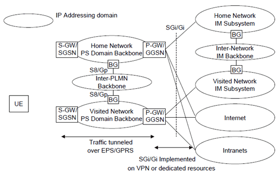
Figure 5-4 below shows an example of the IP Addressing Domains involved in PS-domain and IP-subsystem services.

Figure 5-4: IP Addressing Domains Involved In PS-Domain and IM Services
(⇒ copy of original 3GPP image)
(⇒ copy of original 3GPP image)
Though 3GPP networks can use different IP Addressing Domains as shown above, it is possible that several different IP Addressing Domains fall under a common co-operative management regime. In this case the different IP Addressing Domains may be implemented as a single administrative domain at the operator's discretion, thus using a common IP-address space.
A UE accessing services in either an IM subsystem, the Internet, or an external Intranet, or a combination of these service domains within the same IP network, requires an IP address that is part of the target network's IP Addressing Domain. For each of these IP networks, the IP address is linked to a specific PDP or EPS Bearer context, or set of PDP or EPS Bearer contexts sharing this IP address via a single APN.
When the UE establishes the PDP or EPS Bearer context to access an IP network, it may use an existing PDP or EPS Bearer context if it has an active context with a compatible IP addressing domain and quality of service profile.