Content for TS 23.202 Word version: 18.0.0
4 General
4.1 Limited set of UTRAN Iu mode PLMN connection models
4.2 Limited set of GERAN Iu mode PLMN connection models
4 General p. 6
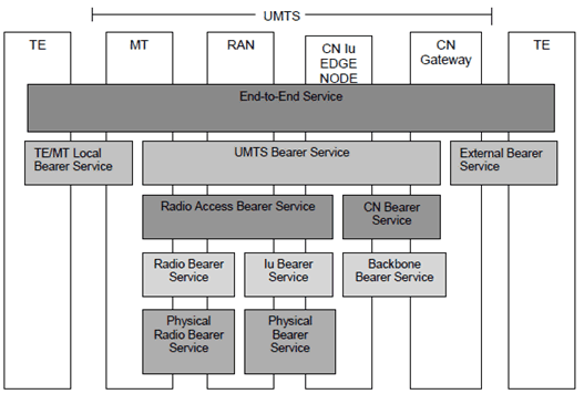
CS data services in UMTS are divided according to TS 22.001 into Bearer Services (TS 22.002) and end-to-end Teleservices (TS 22.003). These services are built on services provided by the Access Network. The Radio Access Bearer Services are invoked through the RNL-SAP provided by the Iu User Plane to the Non-access stratum on the Core Network side, and the corresponding SAP provided by the RLC to the Non-access stratum on the Terminal side. Figure 1 shows the service architecture.
4.1 Limited set of UTRAN Iu mode PLMN connection models p. 7
4.1.1 Transparent data p. 7
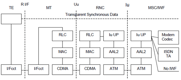
Figure 2 shows the connection model for synchronous transparent CS data. In general all the user data bits are conveyed between the MT and the IWF as they are received from the TE. This implies that the RLC SDU/ Iu UP frame is transparent.
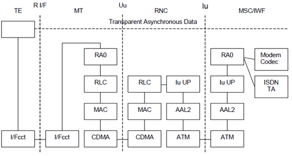
Figure 3 shows the connection model for asynchronous transparent CS data. The rate adaptation function RA0 from TS 44.021 (adapted to the RLC SDU size) is used for converting between asynchronous data and a synchronous bit stream. End-to-end flow control is not applicable in UTRAN Iu mode, thus no status bits are conveyed over RAN/UTRAN (see TS 27.001).
4.1.2 Non-transparent data p. 9
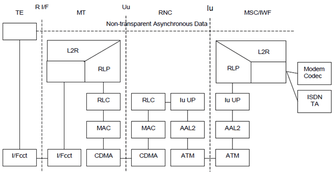
Figure 4 shows the connection model for asynchronous non-transparent CS data.
4.2 Limited set of GERAN Iu mode PLMN connection models p. 9
This subclause gives an overall overview on the PLMN connection models for circuit switched data services in GERAN Iu mode. The stage 2 description is given in TS 43.051. For details concerning the PLMN connection models refer to TS 43.010.
4.2.1 Transparent data p. 9
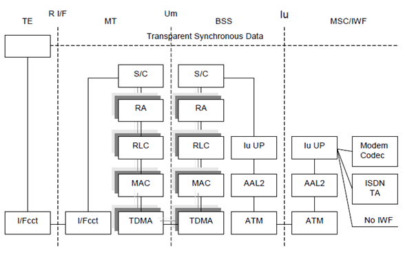
Figure 5 shows the connection model for synchronous transparent CS data. In general all the user data bits are conveyed between the MT and the IWF as they are received from the TE. This implies that the RLC SDU/ Iu UP frame is transparent.
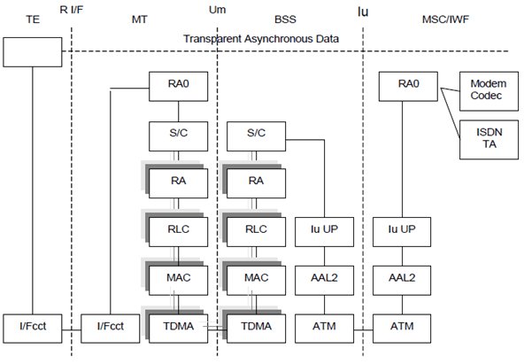
Figure 6 shows the connection model for asynchronous transparent CS data. The rate adaptation function RA0 from TS 44.021 (adapted to the RLC SDU size) is used for converting between asynchronous data and a synchronous bit stream. End-to-end flow control is not applicable in GERAN Iu mode, thus no status bits are conveyed over RAN/GERAN (see TS 27.001).
4.2.2 Non-transparent data p. 11
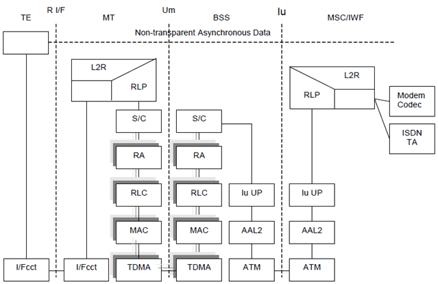
Figure 7 shows the connection model for asynchronous non-transparent CS data.
