Content for TS 23.146 Word version: 18.0.0
4 Network architecture
4.1 Service definition
4.2 Network architecture
5 Reference configuration at the mobile station
5.1 FA functionality
5.2 UMTS facsimile machine functionality
6 Connection types
6.1 Protocol model
6.2 Mobile to mobile calls
6.3 Procedure interrupts
6.4 Radio channel modification
...
...
4 Network architecture p. 8
4.1 Service definition p. 8
The fixed network facsimile group 3 service is an international telematic service for document transmission between two facsimile group 3 terminals.
The service specifications are comprised of two parts:
- the control procedures described in ITU-T Recommendation T.30;
- the document transmission coding described in ITU-T Recommendation T.4.
- a UMTS PLMN as stand alone facility for mobile to mobile communication;
- a UMTS PLMN to have access to fixed networks PSTN and/or ISDN for mobile to/from fixed network communication.
- it uses point to point communication;
- the information transfer mode is circuit, duplex, asynchronous;
- the information transfer capability is alternate speech/ facsimile group 3 or facsimile group 3 only;
- both mobile originated and mobile terminated calls are supported;
- different end to end message speeds as per ITU-T Recommendation T.30 may be used within the same connection to match the appropriate quality requirements;
- use of the standard asynchronous terminal adaptation function for non transparent network support (as per TS 27.002) within the UE is envisaged.
4.2 Network architecture p. 9
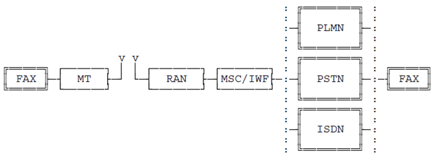
The network architecture applicable to this Teleservice is shown in Figure 1.

It shows the case of mobile to fixed network interworking. For mobile to mobile calls, there would effectively be a loop back within the PLMN using two IWFs.
5 Reference configuration at the mobile station p. 9
The user equipment reference configurations described in this clause are defined as per TS 27.001.

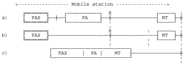
The teleservice definitions in TS 22.003 regard the facsimile group 3 terminal as a 2 wire analogue terminated equipment. In order to connect this to the MT a separate "FA" device is necessary. This configuration, shown in Figure 2 (a), shall be considered as the standard configuration, so that all the existing facsimile group 3 terminals may be connected to the PLMN.
An alternative realization would be to combine a facsimile group 3 terminal and the FA into a special "UMTS facsimile machine", directly providing a digital output. Although such a terminal shall appear to the MT as identical as the FA (i.e. with an identical interface and protocol), it would allow for a significantly smaller and simpler facsimile machine. This configuration is shown in Figure 2 (b).
In addition of course, it is always possible to realize a single device, as per Figure 2 (c), where both the facsimile and mobile termination functions are considered to be part of one integrated unit.
The particular terminal adaptation functions used are those detailed in TS 27.002 for non transparent bearer capability. The interface to the MT used is according to ITU-T Recommendation V.24 with an option for support of TS 27.007 procedures for auto calling and auto answering.
5.1 FA functionality p. 10
The FA block, Figure 3, is intended to specifically complement the facsimile group 3 terminal in order to be able to communicate over a UMTS PLMN.

Whether it has to be a function internal to the UMTS PLMN, or an external accessory associated with the facsimile group 3 terminal, is beyond the scope of the present document, and in any case, does not affect the working of the procedure as described here.
It may be functionally partitioned in two sections:
-
an analogue section, dealing with:
- the modulation and demodulation processes according to ITU-T Recommendation V.21, V.27ter, V.29 and V.17 as explained in ITU-T Recommendation T.4 and T.30;
- handling of the signalling on a 2 wire path to the associated facsimile terminal, including auto calling and auto answering functions where necessary (see clause 7).
-
a digital section, dealing with:
- overall control of the FA;
- where necessary, manipulating the ITU-T Recommendation T.30 protocol as detailed in the present document;
- connection to the TAF using the interface according to ITU-T Recommendation V.24 as described in TS 27.002;
- where necessary, auto calling and auto answering functions according to TS 27.007.
5.2 UMTS facsimile machine functionality p. 10
The special UMTS facsimile machine shown in the UE configuration of Figure 2 (b) is similar to the digital part of the FA, but without any of the analogue portions.
It appears at the ITU-T Recommendation V.24 interface as identical as the FA, i.e. the MT needs to have no knowledge of the particular configuration used.
6 Connection types p. 10
In UMTS, the following connection elements attributes are applicable to these Teleservices.
Connection element:
Non-transparent
Duplex Mode:
Full Duplex
Synchronous/Asynchronous:
Asynchronous
Fixed Network User Rate:
14 400 or 9 600[bit/s]
Wanted Air User Rate:
28 800 or 14 400[bit/s]
Layer 1 and Layer 2 at R reference point are specified in TS 27.002, but not here.
To support the ITU-T Recommendation T.30, requiring different transmission rates, the following strategy shall be implemented:
- the channel on the radio interface in UMTS shall be a channel that is satisfied with a user rate of 28 800 bit/s or 14 400 bit/s;
- the transmission rate between the FA and the associated facsimile terminal at both ends shall be the same, i.e. there shall be only one common end to end transmission rate at any given time;
- the message speed shall be negotiated between T-FAX and R-FAX; this also allows for message speeds of 2 400, 4 800, 7 200, 9 600, or 12 000, 14 400 bit/s to be used;
- the connection between the fax terminals is divided into three logical sections (T-FAX (1) T-FA (2) -R-FA-(3)-R-FAX);
- flag stuffing is applied by the FA towards the associated facsimile terminal within the constraints of ITU-T Recommendation T.30, to keep the data link active whenever a procedure delay occurs;
- the BCS protocol elements and the facsimile coded data are buffered at both FAs , if necessary, to guarantee data integrity;
- a specific FA protocol (FA protocol) is provided between both FAs to cater for appropriate link control.
6.1 Protocol model p. 11
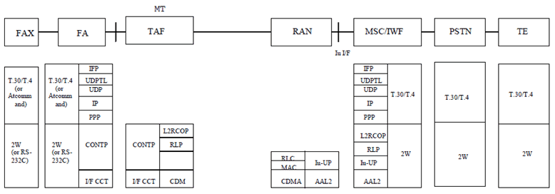
Figure 4 depicts the protocol stack for this Teleservice.
Depending on the particular implementation, the R reference point may not explicitly exist. In this case, the Layer2 protocol between the FA and the TAF and consequently the Layer2 protocol between the FA and the TAF entities operating across this interface may be omitted. The protocol stack at the radio interface, however, is not affected by this consideration, i.e. RLP and L2RCOP always apply.
All protocol modules specific for this Teleservice shall be confined in the FA functions at both the UE and MSC/IWF ends. The TAF shall comply with the specifications TS 27.001 and TS 27.002.


6.2 Mobile to mobile calls p. 12
Tandem operation shall be applied to mobile to mobile calls.
6.3 Procedure interrupts p. 12
Procedure interrupts shall be supported only in Teleservices 61. In the case of Teleservice 62 any attempt to invoke procedure interrupts by MMI on the MT (see clause 6.4) shall have no effect.
6.4 Radio channel modification p. 12
This clause applies to Teleservice 61 only, if a change of the radio channel during the call swapping from speech to facsimile or vice versa is required. For this purpose the in call modification procedure (ICM) as detailed in TS 24.008 is carried out.
The change from speech to facsimile shall be initiated by MMI at the facsimile terminal starting the ICM procedure via MODIFY signalling.