Content for TS 23.034 Word version: 18.0.0
5 HSCSD architecture and transmission
5.1 Air interface
5.2 Functions and information flows
5.2.1 Call establishment procedures
5.2.1.1 Mobile originated call establishment (A/Gb mode)
5.2.1.1a Mobile originated call establishment (GERAN Iu mode)
5.2.1.2 Mobile terminated call establishment (A/Gb mode)
5.2.1.2a Mobile terminated call establishment (GERAN Iu mode)
...
...
5 HSCSD architecture and transmission p. 9
5.1 Air interface p. 9
The HSCSD configuration is a multislot configuration using the TCH/F data channel mapping described in TS 45.002.
Two types of HSCSD configurations exist, symmetric configuration and asymmetric configuration. For both types of configurations the channels may be allocated on either consecutive or non-consecutive time slots taking into account the restrictions defined by the classmark.
An example of the HSCSD operation with two consecutive time slots is shown in Figure 2.
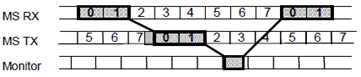
A symmetric HSCSD configuration consists of a bi-directional FACCH and co-allocated bi-directional TCH/F and SACCH channels. An asymmetric HSCSD configuration consists of a bi-direction FACCH and co-allocated uni directional or bi-directional TCH/F and SACCH channels. A bi-directional channel is a channel on which the data is transferred in both uplink and downlink directions. On uni-directional channels for HSCSD the data is transferred in downlink direction, only.
In both symmetric and asymmetric HSCSD configurations one bi-directional channel, the main channel, carries a FACCH used for all the signalling not carried on the SACCH(s).
For HSCSD configuration all SACCHs are synchronized so that idle frames for each time slot coincide.
The classification of mobile stations used for HSCSD shall be based on Multislot classes, described in detail in TS 45.002. Further classification shall be based on the Mobile Station Classmark depending on the supported modulations.
The same frequency hopping sequence and training sequence is used for all the channels in the HSCSD configuration.
The same channel coding is used for all the channels in the HSCSD configuration, though in the enhanced modulation mode, for non-transparent services, it is possible to have one channel coding used in the downlink and another channel coding used in the uplink. Different channel codings for up- and downlink could be applied in three cases, see TS 22.034:
- If the mobile station only supports enhanced modulation in the downlink direction.
- If the mobile station supports enhanced modulation in both directions, but the user indicates preference for uplink or downlink biased channel coding asymmetry.
- If the mobile station supports enhanced modulation in both directions, and the user indicates preference for channel coding symmetry, but the link conditions justifies different channel coding in uplink or downlink.
5.2 Functions and information flows p. 10
The procedures discussed in this clause follow the procedures described in detail in TS 48.008, TS 25.413, TS 25.415, and TS 24.008. Modifications are referred with text in brackets and conditional procedures with dashed line. Normal signalling or signalling presented earlier in the document is drawn with ovals.
5.2.1 Call establishment procedures p. 10
5.2.1.1 Mobile originated call establishment (A/Gb mode) p. 10
Figure 3 depicts the procedures for a successful HSCSD call establishment in mobile originated case in A/Gb mode.
The Multislot class is sent from MS to network using the early classmark sending.
At the call setup the mobile station sends a set of parameters describing the HSCSD characteristics to the network. These parameters and their presence in the Setup message in transparent (T) and non transparent (NT) calls are as follows:
- Other Modem Type, OMT (T/NT);
- Fixed Network User Rate, FNUR (T/NT);
- Acceptable Channel Codings, ACC (including ACC ext.) (T/NT);
- maximum number of traffic channels, Max TCH/F (T/NT);
- User Initiated Modification Indication, UIMI (NT);
- wanted Air Interface User Rate, AIUR (NT), and
- channel coding ASYMmetry indication, ASYM (NT).
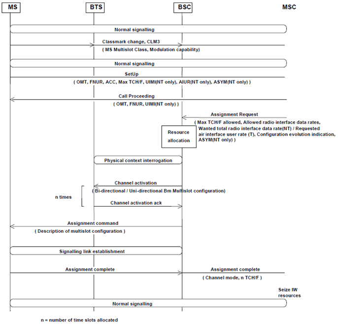
The MSC requests the BSC to allocate the channel configuration using parameters derived from the HSCSD related parameters agreed in the setup phase. Based on these parameters and operator preferences the BSC then allocates a suitable number of channels and a suitable channel coding for the connection.
The following rule for the channel allocation apply:
- The BSS shall try to reach but not exceed, with one exception, the wanted AIUR. The exception is the case when the chosen configuration can reach the wanted AIUR with lower number of TCH/F, e.g. in case AIUR=14,4 kbit/s, max number of TCH/F=3, ACC=TCH/F4.8 and TCH/F9.6, the network shall choose 2 x 9,6 over 3 x 4,8 if the TCH/F9.6 is available in the cell.
- A separate channel activation is applied for each of the HSCSD channels before the selected channel configuration with information of the channel coding is forwarded to the mobile station. When the preference for downlink or uplink biased channel coding asymmetry is indicated by the user, and an asymmetric channel coding connection is set up based on this indication, the BSC shall always assign a TCH/F14.4 channel on the unbiased link of the connection.
- At assignment completion, the BSS informs the MSC of the chosen HSCSD configuration and the MSC may seize the IW resources accordingly.
5.2.1.1a Mobile originated call establishment (GERAN Iu mode) |R5| p. 12
Figure 3a depicts the procedures for a successful HSCSD call establishment in mobile originated case in GERAN Iu mode.
The MS GERAN Iu mode radio access capabilities, including the multislot capabilities of the MS, are sent from the MS to the network during the establishment of the RRC connection.
The BSC includes the GERAN classmark in the RANAP Initial UE message to inform the MSC about the BSS capabilities of the serving cell:
- Acceptable Channel Codings, ACC (including ACC ext.); and
- maximum number of traffic channels, Max TCH/F.
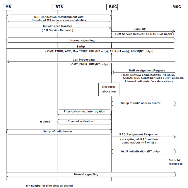
The MSC requests the BSC to allocate a radio access bearer by sending a RANAP RAB Assignment Request message. The RAB parameters in this message are set according to the parameters negotiated between MS and MSC and the GERAN classmark of the serving cell. For non-transparent calls the RAB parameters contain the description of all RAB subflow combinations allowable for the maximum bit rate at the Iu interface, and thus for the maximum possible AIUR that can be allocated by the BSC for this call.
Additionally, the MSC includes a GERAN BSC container, indicating the Max TCH/F allowed and the Allowed radio interface data rates. In this version, the MSC shall indicate only one radio interface data rate as allowed.
Based on these parameters and operator preferences the BSC then allocates a suitable number of channels for the allowed channel coding.
After the successful setup of the radio access bearer, for non-transparent calls the BSC initiates the Iu user plane protocol. In the Iu UP initialisation message the first RAB subflow combination proposed in the list of RAB subflow combinations indicates the RAB subflow combination and thus the AIUR to be used by the IW function when starting the communication phase (see TS 25.415). The BSC shall use the same RAB subflow combination in uplink direction.
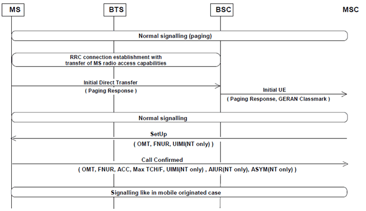
5.2.1.2 Mobile terminated call establishment (A/Gb mode) p. 13
Figure 4 depicts the procedures for a successful HSCSD call establishment in mobile terminated case in A/Gb mode.
At the call setup the network sends the Other Modem Type,OMT, Fixed Network User Rate,FNUR, and User Initiated Modification Indication,UIMI (NT only), parameters to the mobile station.
In reply the mobile station responds to the network with the set of parameters describing the HSCSD characteristics. These parameters and their presence in the Call Confirmed message in transparent (T) and non-transparent (NT) calls are as follows:
- wanted Other Modem Type, OMT (T/NT);
- wanted Fixed Network User Rate, FNUR (T/NT);
- Acceptable Channel Codings, ACC (including ACC ext.) (T/NT);
- maximum number of traffic channels, Max TCH/F (T/NT);
- User Initiated Modification Indication, UIMI (NT);
- wanted Air Interface User Rate, AIUR (NT), and
- channel coding ASYMmetry indication, ASYM (NT).
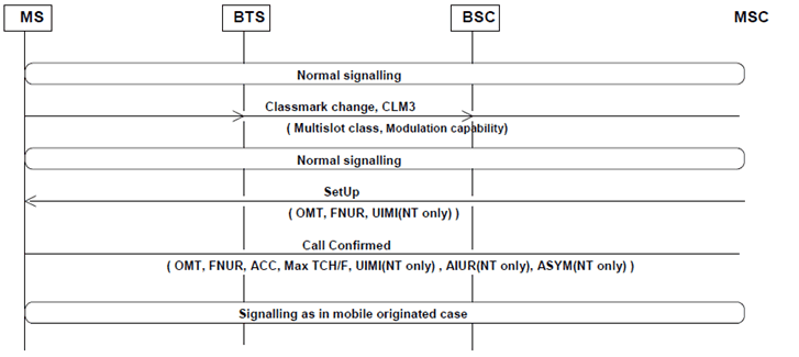
The MSC requests the BSC to allocate the channel configuration using parameters derived from the HSCSD related parameters agreed in the setup phase. Based on these parameters and operator preferences the BSC then allocates a suitable number of channels and a suitable channel coding for the connection.
The same channel allocation rules as in mobile originated case apply.
The same channel activation rules as in mobile originated case apply.
At assignment completion, the BSS informs the MSC of the chosen HSCSD configuration and the MSC may seize the IW resources accordingly.
5.2.1.2a Mobile terminated call establishment (GERAN Iu mode) |R5| p. 14
Figure 4a depicts the procedures for a successful HSCSD call establishment in mobile terminated case in GERAN Iu mode.
For the Setup message and the Call Confirmed message the same rules apply as in A/Gb mode.
The signalling for the setup of the radio bearer and the radio access bearer, and the initialisation of the Iu user plane (NT only) is as in the mobile originated case.
![]()
![]()
![]()