Content for TR 22.835 Word version: 18.2.0
5 Use cases
5.1 Initial access scenario for a network slice service
5.1.1 Description
5.1.2 Pre-conditions
5.1.3 Service Flows
5.1.4 Post-conditions
5.1.5 Existing features partly or fully covering the use case functionality
5.1.6 Potential New Requirements needed to support the use case
5.2 Mobility Handling scenario for a network slice service Use case
5.2.1 Description
5.2.2 Pre-conditions
5.2.3 Service Flows
5.2.4 Post-conditions
5.2.5 Existing features partly or fully covering the use case functionality
5.2.6 Potential New Requirements needed to support the use case
...
...
5 Use cases p. 8
5.1 Initial access scenario for a network slice service p. 8
5.1.1 Description p. 8
Typically, users want for their devices to camp on a cell and be online as soon as possible after power-on. Especially, for 5G System which can provide ultra-low-latency data transport service, it is also important to reduce the time that takes for a device to send a packet after power on, to satisfy overall 5G experience.
5.1.2 Pre-conditions p. 8
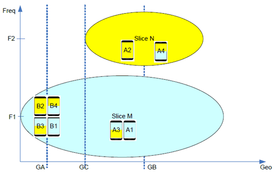
Figure 5.1.2-1 shows the use case scenario where different network slices are configured on different frequency bands at a certain geographical location. In this scenario, all network slices and radio frequency bands belong to the same operator.
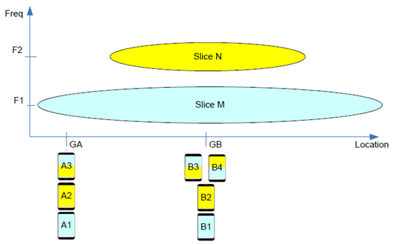
In this use case and Figure 5.1.2-1, following is assumed as pre-condition:
- Initially, UE A1, A2 and A3 are located at location GA and UE B1, B2 and B3 are located at location GB.
- UE A1 and B1 have a subscription only to slice M, and UE A2 and B2 have a subscription only to slice N.
- UE A3, B3 and B4 have a subscription to both slice M and slice N. A3 and B3 have preference to slice M while UE B4 has preference to slice N.
- At location GA, cells are deployed over only frequency F1.
- At location GB, cells are deployed on both frequency F1 and F2.
- Slice M is configured to be provided only if it is accessed over F1.
- Slice N is configured to be provided only if it is accessed over F2.
- Slice N and Slice M are not simultaneously provided to UEs.
5.1.3 Service Flows p. 9
After power-up, following occurs for UE A1, A2 and A3:
- UE A1, A2 and A3 start searching of available cells.
- UE A1, A2 and A3 detect cells on Frequency F1.
- UE A1, A2 and A3 start registration via cells on F1.
- Based on subscription information, A1 and A3 are served with Slice M.
- Because the UE A2 does not have subscription for slice M, A2 stays in limited service state on F1 and does not perform further activity toward the cells on F1.
- UE B1, B2, B3 and B4 start searching of available cells.
- UE B1 and B3 select cells on Frequency F1 and start registration via the selected cell. Based on subscription information, the network provides services to UE B1 and B3 with Slice M over F1.
- UE B2 and B4 switches to Frequency F2 as soon as possible and selects cells on Frequency F2 and start registration. Because the network does not provide service of F1, UE B2 needs to minimize unnecessary attempt on F1. Similarly, the preferred slice is provided over F1 than F2, the UE B4 needs to move to F2 as soon as possible.
5.1.4 Post-conditions p. 9
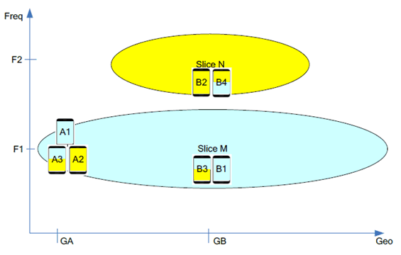
Figure 5.1.4-1 shows on which frequency each UE camps on finally to get desirable network slice service.
5.1.5 Existing features partly or fully covering the use case functionality p. 10
When a UE is located in an area where there is an authorized network slice for the UE, the 5G system shall be able to efficiently enable the UE to camp on radio resources where the network slice is provided.
5.1.6 Potential New Requirements needed to support the use case p. 10
[PR.5.1.6-2]
When a UE is located in an area where there is at least one authorized network slice for the UE, the 5G system shall be able to minimize the time for the UE to access the network slices which is most suitable based on e.g., location of the UE, active applications, UE capability, frequency used by the network slice.
[PR.5.1.6-1]
When a UE is located in an area where there is no authorized network slice for the UE, the 5G system shall support a mechanism to efficiently enable the UE to minimize power consumption (e.g., cell search, cell measurement).
5.2 Mobility Handling scenario for a network slice service Use case p. 10
5.2.1 Description p. 10
Due to various reasons, the availability of cell on a certain frequency is not homogeneous. For example, in an area where lots of people gather e.g. like office district, operator may deploy cells on all available frequencies. On the other hand, in an area whether population density is low, only part of owned frequency bands will be used to provide connectivity service.
In this use case, the above situation is investigated with movement of terminals. I.e., as mobile devices move from an area where some frequency band is used to deploy cells to an area where other frequency band is used to deploy cells. Even in this case, it is important to reduce the time that the UE is not provided with network slice service which it deserves.
5.2.2 Pre-conditions p. 10
Figure 5.2.2-1 shows the use case scenario where different network slices are configured on different frequency bands at a certain geographical location. In this scenario, all network slices and radio frequency bands belong to the same operator.
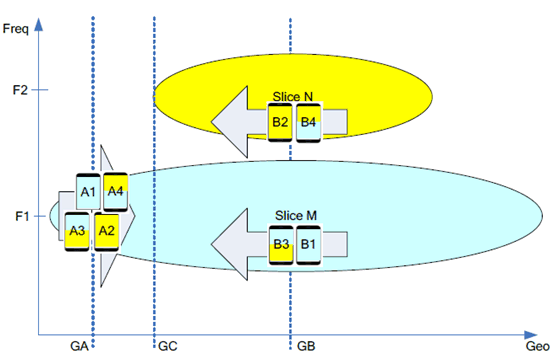
In this use case and Figure 5.2.2-1, following is assumed as pre-condition:
-
Location:
- Initially, UE A1, A2, A3 and A4 are located at location GA.
- Initially, UE B1, B2, B3 and B4 are located at location GB.
-
Subscription:
- UE A1 and B1 have a subscription only to slice M.
- UE A2 and B2 have a subscription only to slice N.
- UE A3, A4, B3 and B4 have a subscription to both slice M and slice N. A3 and B3 have preference to slice M while A4 and B4 have preference to slice N.
-
Deployment:
- At location GA, cells are available over frequency F1, but not over frequency F2.
- At location GB, cells are available over both F1 and F2.
- Slice M is configured to be available over only F1 and Slice N is configured to be available over only F2. Slice N is available only within a certain location, e.g. within a factory. Slice M is available in wide area
- Due to isolation policy, slice N and slice M are strictly isolated. I.e., hardware is not shared between the slices.
- Based on application policy, some applications are allowed to be served over either slice N and slice M, while some applications are restricted to use only specific slice.
-
Initial condition:
- A1, A2, A3, A4, B1 and B3 are on F1. B2 and B4 are on F2.
5.2.3 Service Flows p. 11
Following is potential service flow for UE A1, A2, A3 and A4:
- UE A1, A2, A3 and A4 are on Frequency F1. UE A1, A3 and A4 are served with Slice M, but UE A2 is in limited service state, due to lack of subscription for slice M. Accordingly, the UE A2 needs to minimize power consumption, e.g., that may be caused due to unnecessary monitoring of other cells.
- UE A1, A2, A3 and A4 move toward GB via GC.
- UE A1 and A3 continues to be serviced with Slice M via Frequency F1 at location GC and GB.
- At location GC, the UE A2 starts searching cells on Frequency F2. After moving to F2, the UE A2 starts to be served with Slice N. This should occur as soon as possible, because the UE A2 was out of service from location GA to location GC.
- Somewhere between location GC and location GB, the UE A4 moves to Frequency F2 and starts to be served with Slice N, because the UE A4 prefers Slice N to Slice M. To minimize impact on the ongoing services over Slice M, when the UE A4 moves to Frequency F2 can be dependent on many other factors such as active applications on each slice.
- UE B2 and B4 are on Frequency F2 and served with Slice N. UE B1 and B3 are on Frequency F1 and served with Slice M.
- Due to lack of subscription of network slices provided over F1, the UE B2 may be allowed to minimize power consumption that may be caused, e.g., due to monitoring cells of other frequency F1.
- UE B1, B2, B3 and B4 move toward GA via GC.
- UE B1 and B3 are still serviced with Slice M via Frequency F1 from location GC to location GA.
- As the UE B2 moves across location GC and moves toward GA, the UE B2 will eventually lose connectivity service because there is no available cell on Frequency F2 and there is no allowed network slice on F1 for the UE B2. In this case, it is desirable for the UE B2 to prepare for the sudden loss of connectivity service. Especially, if the service over slice N is kind of URLLC service that is available only within some specific places such as within a smart factory, the sudden loss of connectivity should be avoided as much as possible. Thus, before the UE crosses the location GC, the UE B2 needs to be given with grace time to prepare for the loss of connectivity, e.g. termination of ongoing applications.
- As the UE B4 approaches location GC, the UE B4 needs to move to Frequency F1. As the UE B4 moved to Frequency F1, the UE starts to be served with Slice M. Because the UE B4 prefers Slice N to Slice M, the transition from F2 to F1 should not occur unnecessarily too early. On the other hand, if the transition from F2 to F1 occurs after the UE B4 crosses the location GC, there is potential loss of connectivity. Thus, the transition from F2 to F1 should occur before crossing location GC. To minimize impact on the ongoing services over Slice N, it may also be better for the UE to be notified in advance of the transition from F2 to F1. This may enable for the UE to do smooth adjustment of services, such as termination of application or relocation of application to one slice to another.
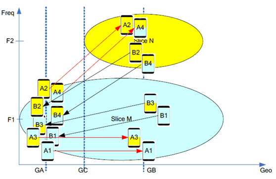
Figure 5.2.3-1 shows the UE movement.
5.2.4 Post-conditions p. 13
After passing through location GC, following are desired results after mobility:
- UE A1, B1, A3 and B3 keep on staying on F1 and are provided with slice M.
- UE A2 moves to F2 and is now provided with slice N.
- UE A4 moves to F2 and is now provided with slice N and is not provided anymore with slice M.
- UE B2 camps on F1, is disconnected from slice N and is in limited state.
- UE B4 moves to F1, is provided with slice M and not any more with slice N.
5.2.5 Existing features partly or fully covering the use case functionality p. 14
When a UE moves from an area where there is no authorized network slice for the UE to an area where there is at least one authorized network slice for the UE, the 3GPP system shall be able to efficiently enable the UE to access the authorized network slices as soon as possible.
5.2.6 Potential New Requirements needed to support the use case p. 14
[PR.5.2.6-1]
When a UE moves out of the service area of a network slice for an active application, the 5G system shall be able to minimize impact on the applications (e.g., providing early notification).
![]()
![]()
![]()