Content for TS 23.402 Word version: 18.3.0
0…
4…
4.2…
4.2.2
4.2.3
4.3…
4.4…
4.5…
4.5.7…
4.6…
4.7…
4.7.2…
4.8…
4.8.2a…
4.9…
5…
5.2…
5.4…
5.5
5.6…
5.7…
5.8…
6…
6.2…
6.3
6.4…
6.4.3…
6.5…
6.6…
6.7…
6.8…
6.10…
6.13…
6.15…
7…
7.2…
7.3
7.4…
7.5…
7.6…
7.8…
7.10…
8…
8.2.1.2
8.2.1.3…
8.2.2
8.2.3…
8.2.6…
8.3…
8.4…
8.5…
9…
9.3…
9.4…
10…
13…
16…
16.1.2…
16.1.6…
16.2…
16.2.1a…
16.3…
16.4…
16.7…
16.8…
16.10…
17…
A…
C…
E…
9.3 Optimized Active Handover: E-UTRAN Access to cdma2000 HRPD Access
9.3.0 Introduction
9.3.1 Pre-registration Phase
9.3.2 Handover Phase
...
...
9.3 Optimized Active Handover: E-UTRAN Access to cdma2000 HRPD Access p. 228
9.3.0 Introduction p. 228
This clause describes the Optimised Handover from E-UTRAN Access to cdma2000 HRPD Access in two phases, pre-registration and the actual handover. In pre-registration phase the UE registers to the cdma2000 HRPD Access, while the UE remains to be connected to the E-UTRAN. The pre-registration may take place well in advance of the need to make the actual handover. In the handover phase, the connection is handed over to cdma2000 HRPD Access, and the UE leaves E-UTRAN.
9.3.1 Pre-registration Phase p. 228
Figure 9.3.1-1 illustrates a high-level call flow for the optimised E-UTRAN to HRPD handover procedure, Pre-registration phase.
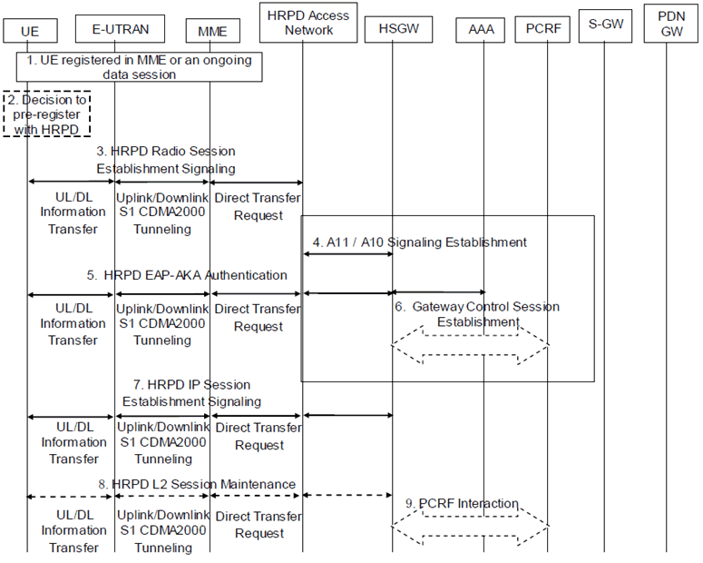
Step 1.
The UE is registered with E-UTRAN/MME. It may have an ongoing data session established over EPS/E-UTRAN access.
Step 2.
Based on a Radio Layer trigger (e.g., an indication from the E-UTRAN when the UE is in connected state or an indication over the broadcast channel), the UE decides to initiate a pre-registration procedure with potential target HRPD access. The pre-registration procedure allows the UE to establish and maintain a dormant session in the target HRPD access, while attached to the E-UTRAN/MME.
Step 3.
Registration to the HRPD is achieved by exchanging a series of HRPD messages between the UE and the HRPD Access Network. The HRPD signalling that is tunnelled transparently over the E-UTRAN and EPC creates an HRPD session context between the UE and the HRPD Access Network. The procedures described below are used in steps 3, 5, 8 and 9.
The UE generates an UL Information Transfer message (UL HRPD message). The UL HRPD message is transferred from the UE to the eNodeB as a parameter in the UL Information Transfer.
The eNodeB sends Uplink S1 CDMA2000 Tunnelling message (UL HRPD message, Sector ID) to the MME. The SectorID is statically configured in the eNodeB.
The MME selects an HRPD access node address. In order to be able to distinguish S101 signalling transactions belonging to different UEs, an S101 Session ID is used to identify signalling related to that UE on S101. The MME sends a Direct Transfer Request message (S101 Session ID, SectorID, UL HRPD message) to the HRPD access node. The MME determines the correct HRPD access node entity and address from the SectorID.
The HRPD Access Network sends signalling in the DL direction to the MME using Direct Transfer Request message (S101 Session ID, DL HRPD message). The S101 Session ID is used to associate the signalling to a particular UE.
The MME sends the information on to the eNodeB using the Downlink S1 CDMA2000 Tunnelling message (DL HRPD message).
The eNodeB uses the DL information transfer message (DL HRPD message) to transport the signalling the UE.
If UE is handing over emergency sessions to HRPD access, the UE informs the HRPD access that it is an emergency handover. In case the UE is in limited service state and does not have an IMSI or its IMSI is unauthenticated, IMEI is used as a Session ID. If the IMSI is unauthenticated, the IMSI is also provided on the S101 tunnel to the HRPD access with an indication that it is unauthenticated.
Step 4.
The HRPD Access Network creates a signalling relationship with the HS-GW for the UE with interactions in HRPD network A10 / A11 interfaces.
If the HRPD Access Node is not configured to support emergency handovers, then it shall reject any handover request that indicates Emergency Handover.
Step 5.
The UE, HS-GW, and 3GPP AAA exchange EAP-AKA' signalling to authenticate the UE on the HRPD system. The HS-GW receives the APN(s) and PDN-GW identity(es) information from AAA during authentication.
If the UE is performing an Emergency handover to HRPD access for emergency service and the HRPD access supports Emergency handover, the HPRD access skips the authentication procedure or the HRPD access accepts that the authentication may fail and continues the handover procedure. A statically configured PDN-GW is selected by the HRPD access for the UE for unauthenticated UEs.
Step 6.
The HS-GW initiates a Gateway Control Session Establishment Procedure with the PCRF as specified in TS 23.203. If the HS-GW supports UE/NW bearer control mode, the PCRF provides the rules required for the HS-GW to perform the bearer binding for all the active sessions the UE may establish as a result of the handover procedure. For each PDN connection, if the UE has acquired an IPv6 prefix via the 3GPP access, the PCRF returns the IPv6 prefix of UE to the HSGW and the HSGW includes it in the TFT sent to the UE.
Step 7.
The UE and HS-GW exchange signalling to establish context to support the bearer traffic environment in use over the E-UTRAN.
Step 8.
At any time prior to the Handover Phase, if session maintenance activity is required, the UE or HRPD access network shall perform session maintenance signalling by tunnelling the HRPD session maintenance messages over the S101. If QoS parameters require updating, then this step includes the PCRF interaction. The MME uses the S101 Session ID to identify the UE context over the S101 interface.
9.3.2 Handover Phase p. 231
Figure 9.3.2-1 illustrates a high-level call flow for the optimised E-UTRAN to HRPD handover procedure, Handover phase. The prerequisite of the handover phase is the successfully performed Pre-registration phase as it is specified in clause 9.3.1.
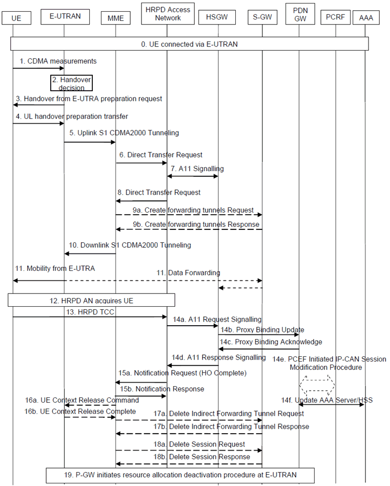
Step 0.
Ongoing session established over EPS/E-UTRAN access.
Step 1.
The eNodeB receives measurement reports from the UE.
Step 2.
The eNodeB makes the handover decision.
Step 3.
The handover decision is signalled to the UE with Handover from E-UTRA preparation request message.
Step 4.
UE sends an UL handover preparation transfer message (HRPD message starting HO access) to the eNodeB. The HRPD message starting HO access will be carried transparently to the HRPD access node, and its purpose is to request information for accessing an HRPD traffic channel. The message indicates to the eNodeB that the UE is responding to the Handover from E-UTRA preparation request message, and is requesting information for accessing an HRPD traffic channel.
Step 5.
The eNodeB sends the Uplink S1 CDMA2000 Tunnelling message (HRPD message starting HO access, and SectorID, CDMA2000 HO Required Indication) to the MME. The SectorID is statically configured in the eNodeB. The eNodeB will also include CDMA2000 HO Required Indication IE to Uplink S1 CDMA2000 Tunnelling message, which indicates to the MME that the handover preparation has started.
Step 6.
When receiving Uplink S1 CDMA2000 Tunnelling message with CDMA2000 HO Required Indication the MME determines an HRPD access node address based on the SectorID. An S101 Session ID is used to identify signalling related to that UE on S101. The MME sends a Direct Transfer Request message (S101 Session ID, SectorID, PDN-GW Identity(es), GRE key(s) for uplink traffic, APN(s), HRPD message starting HO access) to the HRPD access node.
When GTP based S5/S8 is used in the EPS, the MME creates the uplink GRE keys from the uplink TEIDs of the default bearers using a standardized algorithm. In this way only one GRE key per PDN connection is created. The PDN-GW shall be able to identify any PDN connection based on the GRE key created from the uplink TEID of the default bearer of that PDN connection.
Step 7.
The HRPD access network allocates the requested radio access resources, and requests a forwarding address from HS-GW. The information sent in the request from the HRPD access network to HS-GW includes APN(s), PDN-GW Identity(es) and GRE key(s) for uplink traffic. The response includes the HS-GW Address and GRE key(s) for forwarded traffic on S103. There is one GRE key for each PDN connection for which traffic is to be forwarded.
Step 8.
The HRPD access network sends the Direct Transfer Request message (S101 Session ID, HRPD message with HO access information, HS-GW Address and GRE key(s) for forwarded traffic, CDMA2000 HO Status) to the MME. The HS-GW Address and GRE key(s) for forwarded traffic are sent if data forwarding applies. If the HRPD access network did not allocate the resources as requested, this will be indicated to the MME and eNodeB with the CDMA2000 HO Status IE, and the embedded HRPD message indicates the failure to the UE.
Step 9a.
If Direct Transfer Request message included HS-GW Address and GRE key(s) for forwarded traffic, the MME determines which of the S1-U bearers should be forwarded to the HRPD and configures resources for indirect data forwarding by sending Create Forwarding Tunnel Request (HS-GW address, GRE key(s) for forwarded traffic, EPS bearer ID(s) subject to forwarding) to the Serving-GW.
The MME shall select the same Serving-GW which is used as the anchor point for the UE to perform the data forwarding.
Step 9b.
The Serving-GW confirms data forwarding resources for S103 and allocates forwarding address for S1 in Create Forwarding Tunnel Response (cause, S-GW address, S1-U uplink TEID(s)). The S1-U uplink TEIDs are provided one per S1-U bearers subject to forwarding.
Step 10.
The MME sends the Downlink S1 CDMA2000 Tunnelling message (HRPD message with HO access information, S-GW address, S1-U uplink TEID(s), CDMA2000 HO Status) to the E-UTRAN. If the CDMA2000 HO Status indicates that handover preparation failed, the Downlink S1 CDMA2000 Tunnelling message will be sent with appropriate cause, and the embedded HRPD message that indicates the failure to the UE. The message from the MME provides the eNodeB also with the data forwarding S1-U uplink TEIDs allocated at the Serving-GW if data forwarding applies.
Step 11.
The E-UTRAN forwards the HRPD message with HO access information to the UE in Mobility from E-UTRA message. This is perceived by the UE as a Handover Command message. If handover preparation failed, DL Information transfer message will be sent instead, with the embedded HRPD message that indicates the failure to the UE.
If data forwarding applies, the E-UTRAN starts forwarding received downlink data to the S-GW on a per-S1-U bearer forwarding tunnel, which then forwards these packets on a per-PDN per-UE S103 tunnel to the HS-GW. The forwarding starts at the same moment as the Mobility from E-UTRA message is sent to the UE.
Step 12.
The UE retunes to the HRPD radio access network and performs traffic channel acquisition.
Step 13.
The UE sends an HRPD Traffic Channel Complete (TCC) message to the HRPD access network.
Step 14a-f.
The E-UTRAN triggers switching the flow in the EPC with the following sequence:
Step 14a.
Step 15a.
The HRPD access network sends A11 request signalling to HS-GW to start setting up the U-Plane connection between the HRPD access network and HS-GW.
Step 14b.
The HS-GW sends Proxy Binding Update to PDN-GW. The HS-GW sends the all zero IPv4 Home Address (0.0.0.0) or all zero IPv6 Home Prefix (0::/0) in the PBU message. In order to support session continuity, the P-GW performs the Binding Cache entry existence test based on the NAI and assigns the same IPv4 Home Address and/or IPv6 Home Prefix to the UE and acknowledge in the PBA message.
Step 14c.
The PDN-GW switches the flow from Serving-GW to HS-GW, and sends Proxy Binding Acknowledge to HS-GW, including the Charging ID for the PDN connection.
Step 14d.
The HS-GW responses with A11 response signalling to the HRPD access network.
Step 14e.
The PDN-GW executes a PCEF-Initiated IP-CAN Session Modification Procedure with the PCRF as specified in TS 23.203 to obtain the rules required for the PDN-GW to function as the PCEF for all the active IP sessions the UE has established with new IP-CAN type. Otherwise, information configured with the P-GW may be used to determine policy. Since Steps 14c and 14e are both triggered by the Proxy Binding Update in Step 14b, Steps 14c and 14e may occur in parallel.
Step 14f.
The PDN-GW informs the 3GPP AAA Server of its PDN-GW identity and the APN corresponding to the UE's PDN Connection and obtains authorization information from the 3GPP AAA Server. The message includes information that identifies the PLMN in which the PDN-GW is located. The 3GPP AAA Server may update the information registered in the HSS as described in clause 12.
For a multiple PDN connection, steps 14b-14c and 14e-14f are performed for each PDN connection.
Multiple PDN connections to the same APN can be supported using PDN connection identities in the same way as it is specified for S2a procedures.
The HRPD access network sends a Notification Request (HO Complete, S101 session ID) message to the MME (including the S101 session ID to identify the UE context).
Step 15b.
The MME responds by sending a Notification Response (S101 session ID) to the HRPD access network.
If data forwarding was not applied in step 9, the MME shall skip step 17, and shall perform steps 16 and 18.
If data forwarding was applied in step 9, a timer in MME is started to supervise when the EPS bearer resources in the Serving-GW and the temporary resources used for indirect data forwarding in the Serving-GW shall be released. The uses of the timer is defined in TS 23.401. The MME shall perform steps 16, 17 and 18 upon the timer expiry.
If the EPS bearer resources release is triggered by a Delete Bearer Request message (from step 19) received before the timer expiry, the MME shall stop the timer and skip steps 16, 17 and 18.
Step 16a.
The MME releases the UE context in the source E-UTRAN by sending a UE Context Release Command message to the eNodeB.
Step 16b.
The source eNodeB releases its bearer resources related to the UE and responds with a UE Context Release Complete message.
Step 17a.
The MME sends a Delete Indirect Data Forwarding Tunnel Request message to the Serving-GW.
Step 17b.
The Serving-GW releases the temporary resources used for indirect data forwarding which were allocated at step 9. The Serving-GW acknowledges with Delete Indirect Data Forwarding Tunnel Response message.
Step 18a.
The MME releases the EPS bearer resources in the Serving-GW by sending a Delete Session Request message to the Serving-GW. The MME shall indicate to the Serving-GW that the Serving-GW shall not initiate a delete procedure towards the PDN-GW.
Step 18b.
The Serving-GW acknowledges resource removal with Delete Session Response (Cause) message.
Step 19.
At any time after step 14c, the PDN-GW shall initiate the PDN-GW Initiated PDN Disconnection procedure at E-UTRAN as defined in clause 5.6.2.2 or the PDN-GW Initiated Bearer Deactivation procedure as defined in clause 5.4.4.1 of TS 23.401. If data forwarding was applied, the forwarding tunnel established in step 9 shall be also released in this step.
![]()
![]()
![]()