Content for TS 23.402 Word version: 18.3.0
0…
4…
4.2…
4.2.2
4.2.3
4.3…
4.4…
4.5…
4.5.7…
4.6…
4.7…
4.7.2…
4.8…
4.8.2a…
4.9…
5…
5.2…
5.4…
5.5
5.6…
5.7…
5.8…
6…
6.2…
6.3
6.4…
6.4.3…
6.5…
6.6…
6.7…
6.8…
6.10…
6.13…
6.15…
7…
7.2…
7.3
7.4…
7.5…
7.6…
7.8…
7.10…
8…
8.2.1.2
8.2.1.3…
8.2.2
8.2.3…
8.2.6…
8.3…
8.4…
8.5…
9…
9.3…
9.4…
10…
13…
16…
16.1.2…
16.1.6…
16.2…
16.2.1a…
16.3…
16.4…
16.7…
16.8…
16.10…
17…
A…
C…
E…
6.10 PDN-GW reallocation upon attach on S2c
6.11 S2c Bootstrapping via DSMIPv6 Home Link over a Trusted Access
6.12 PDN-GW initiated Resource Allocation Deactivation
6.12.1 PDN-GW initiated Resource Allocation Deactivation with S2a PMIP
6.12.2 PDN-GW initiated Resource Allocation Deactivation with S2a MIPv4
6.12.3 PDN-GW initiated Resource Allocation Deactivation for Chained PMIP-based S8-S2a Roaming
...
...
6.10 PDN-GW reallocation upon attach on S2c p. 147
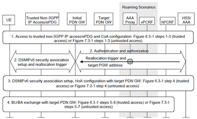
The PDN-GW reallocation procedure depicted in Figure 6.10-1 can be used by the HSS/AAA to force the assignment of a new PDN-GW to the UE upon attach with DSMIPv6 in a trusted or untrusted non-3GPP IP access. The decision on whether to trigger PDN-GW reallocation is taken by the HSS/AAA according to the principles described in clause 4.5.2.

The following is a detailed description of the involved steps:
Step 1.
The UE authenticates in the trusted non-3GPP access, or establishes the IPsec tunnel with the ePDG, and obtains a local IP address to be used as care-of address for DSMIPv6.
Step 2.
The UE establishes the DSMIPv6 SA with the initially discovered PDN-GW. This implies an AAA exchange with the HSS/AAA. The HSS/AAA triggers the reallocation of the PDN-GW and the APN associated with the UE's PDN Connection by piggybacking a reallocation indication and the target PDN-GW identity in the AAA exchange. In the signalling from the PDN-GW to the UE, the PDN-GW indicates reallocation, assigns no IPv6 prefix to the UE and includes the IP address of the target PDN-GW.
If the target PDN-GW identity is stored in the HSS in form of the IP address, then this IP address can be transferred to the UE directly. If the target PDN-GW identity is stored in the HSS in form of the PDN-GW FQDN, the initial PDN-GW shall derive the IP address of the HA functionality of the target PDN-GW from the PDN-GW FQDN provided by the AAA server and provide it to the UE.
Step 3.
The UE establishes the DSMIPv6 SA with the target PDN-GW provided by the network during step 2.
Step 4.
The UE performs the DSMIPv6 registration with the target PDN-GW.
6.11 S2c Bootstrapping via DSMIPv6 Home Link over a Trusted Access p. 148
When the UE is connected on a trusted non-3GPP access considered to be DSMIPv6 home link for the UE based on clause 4.5.6, the UE may trigger the establishment of S2c IKEv2 SA, e.g. to optimize future handovers to other accesses using S2c. For each PDN connection, the S2c IKEv2 SA establishment has to be performed separately.
Once the UE is attached to the PDN over the trusted non-3GPP access, the procedure describing the bootstrapping is in clause 15.1.
6.12 PDN-GW initiated Resource Allocation Deactivation p. 148
6.12.1 PDN-GW initiated Resource Allocation Deactivation with S2a PMIP p. 148
This procedure is performed to release all the resources associated with the PDN address, for example, due to IP-CAN session modification requests from the PCRF or due to handover from Non-3GPP to 3GPP. When it is performed for an handover, the connections associated with the PDN address are released, but the PDN address is kept in the PDN-GW.

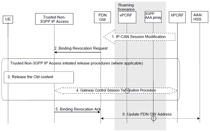
This procedure applies to the Non-Roaming (Figure 4.2.2-1), Roaming (Figure 4.2.3-1) and Local Breakout (Figure 4.2.3-4) cases. For the Roaming and Local Breakout cases, the vPCRF forwards messages between the non-3GPP IP access and the hPCRF. In the Local Breakout case, the vPCRF forwards messages between the PDN-GW and the hPCRF. In the non-roaming case, the vPCRF is not involved at all.
The optional interaction steps between the gateways and the PCRF in the procedures in Figure 6.12.1-1 only occur if dynamic policy provisioning is deployed. Otherwise policy may be statically configured with the gateway.
Step 1.
If dynamic PCC is deployed, the PDN-GW initiated Resource Allocation Deactivation procedure may for example be triggered due to 'IP-CAN session Modification procedure', as defined in TS 23.203. In this case, the resources associated with the PDN connection in the PDN-GW are released.
The PDN-GW initiated Resource Allocation Deactivation can also be triggered during handovers from Non-3GPP to 3GPP.
Step 2.
The PDN-GW sends a Binding Revocation Indication message to the trusted non-3GPP IP access.
Step 3.
The resources may be released in the trusted non-3GPP IP access, according to an access specific, trusted non-3GPP IP access initiated, release mechanism.
Step 4.
If the resources are released in the trusted non-3GPP IP access, the trusted non-3GPP IP access initiates a Gateway Control Session Termination Procedure with the PCRF as specified in TS 23.203.
Step 5.
The trusted non-3GPP IP access returns a Binding Revocation Acknowledgement message to the PDN-GW.
Step 6.
In the case where the resources corresponding to the PDN connection are released in PDN-GW, the PDN-GW informs the 3GPP AAA Server of the PDN disconnection. If the UE no longer has any context in the 3GPP AAA Server, the 3GPP AAA Server notifies the HSS as described in clause 12.1.2.
6.12.2 PDN-GW initiated Resource Allocation Deactivation with S2a MIPv4 p. 149
This procedure is performed to release all resource allocations associated with the PDN address, for example, due to IP-CAN session modification requests from the PCRF or due to handover without optimization from Non-3GPP to 3GPP. When it is performed for an handover, the connections associated with the PDN address are released, but the PDN address is kept in the PDN-GW.

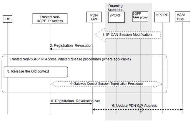
Figure 6.12.2-1: PDN-GW Initiated Registration Revocation over S2a MIPv4 interface
(⇒ copy of original 3GPP image)
(⇒ copy of original 3GPP image)
This procedure applies to the Non-Roaming (Figure 4.2.2-1), Roaming (Figure 4.2.3-1) and Local Breakout (Figure 4.2.3-4) cases. For the Roaming and Local Breakout cases, the vPCRF forwards messages between the non-3GPP access and the hPCRF. In the Local Breakout case, the vPCRF forwards messages between the PDN-GW and the hPCRF. In the non-roaming case, the vPCRF is not involved at all.
The optional interaction steps between the gateways and the PCRF in the procedures in Figure 6.12.2-1 only occur if dynamic policy provisioning is deployed. Otherwise policy may be statically configured with the gateway.
Step 1.
If dynamic PCC is deployed, the PDN-GW initiated Resource Allocation Deactivation procedure may for example be triggered due to 'IP-CAN session Modification procedure' as defined in TS 23.203. In this case the resources associated with the PDN connection in the PDN-GW are released.
The PDN-GW initiated Resource Allocation Deactivation can also be triggered during handovers from Non-3GPP to 3GPP.
Step 2.
If the revocation support has been negotiated, the PDN-GW sends a Registration Revocation message to the trusted non-3GPP IP access as defined in RFC 3543.
Step 3.
The resources may be released in the trusted non-3GPP IP access, according to an access specific, trusted non-3GPP IP access initiated, release mechanism.
Step 4.
The Trusted Non-3GPP Access Network detects the UE's leaving and initiates a Gateway Control Session Termination Procedure with the PCRF as specified in TS 23.203. The Trusted Non-3GPP Access Network no longer applies QoS policy to service data flows for this UE.
Step 5.
The trusted non-3GPP IP access returns a Registration Revocation Acknowledgement message to the PDN-GW.
Step 6.
In the case where the resources corresponding to the PDN connection are released in PDN-GW, the PDN-GW informs the 3GPP AAA Server of the PDN disconnection. If the UE no longer has any context in the 3GPP AAA Server, the 3GPP AAA Server notifies the HSS as described in clause 12.1.2.
6.12.3 PDN-GW initiated Resource Allocation Deactivation for Chained PMIP-based S8-S2a Roaming p. 150
This clause defines the PDN-GW initiated resource allocation deactivation for chained PMIP-based S8-S2a roaming. This procedure also applies for PMIP-based S8-S2b chaining.

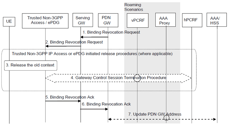
Figure 6.12.3-1: PDN-GW Initiated Binding Revocation for Chained PMIP-based S8-S2a Roaming Case
(⇒ copy of original 3GPP image)
(⇒ copy of original 3GPP image)
The optional interaction step between the gateways and the PCRF in the procedures in Figure 6.12.3-1 occur only if dynamic policy provisioning is deployed. Otherwise policies may be statically configured in the gateway.
Step 1.
The PDN-GW sends a Binding Revocation Indication message to the MAG function in the Serving-GW.
Step 2.
The Serving-GW sends a corresponding Binding Revocation Indication message to the MAG function of the trusted non-3GPP IP access or ePDG.
Step 3.
The trusted non-3GPP IP access or ePDG may release allocated resources in the non-3GPP IP access according to access specific release mechanisms.
Step 4.
In case a Gateway Control Session between the trusted non-3GPP access or ePDG and hPCRF exists, the Gateway Control Session Termination procedure, as specified in TS 23.203, is performed.
Step 5.
The MAG function of the trusted non-3GPP IP access or ePDG returns a Binding Revocation Acknowledgement message to the Serving-GW.
Step 6.
The MAG function of the Serving-GW or ePDG sends a corresponding Binding Revocation Acknowledgement message to the PDN-GW.
Step 7.
In the case where the resources corresponding to the PDN connection are released in the PDN-GW, the PDN-GW informs the 3GPP AAA Server of the PDN disconnection. If the UE no longer has any context in the 3GPP AAA Server, the 3GPP AAA Server notifies the HSS as described in clause 12.1.2.