Content for TS 23.402 Word version: 18.3.0
0…
4…
4.2…
4.2.2
4.2.3
4.3…
4.4…
4.5…
4.5.7…
4.6…
4.7…
4.7.2…
4.8…
4.8.2a…
4.9…
5…
5.2…
5.4…
5.5
5.6…
5.7…
5.8…
6…
6.2…
6.3
6.4…
6.4.3…
6.5…
6.6…
6.7…
6.8…
6.10…
6.13…
6.15…
7…
7.2…
7.3
7.4…
7.5…
7.6…
7.8…
7.10…
8…
8.2.1.2
8.2.1.3…
8.2.2
8.2.3…
8.2.6…
8.3…
8.4…
8.5…
9…
9.3…
9.4…
10…
13…
16…
16.1.2…
16.1.6…
16.2…
16.2.1a…
16.3…
16.4…
16.7…
16.8…
16.10…
17…
A…
C…
E…
6.8 UE-initiated Connectivity to Additional PDN
6.8.1 UE-initiated Connectivity to Additional PDN with PMIPv6 on S2a
6.8.2 UE-initiated Connectivity to Additional PDN with MIPv4 FACoA on S2a
6.8.3 UE-initiated Connectivity to Additional PDN from Trusted Non-3GPP IP Access with DSMIPv6 on S2c
...
...
6.8 UE-initiated Connectivity to Additional PDN p. 142
6.8.1 UE-initiated Connectivity to Additional PDN with PMIPv6 on S2a p. 142
6.8.1.0 General |R10| p. 142
This procedure is used to request for connectivity to an additional PDN over trusted non-3GPP access with PMIPv6 on S2a when the UE already has active PDN connections over such trusted access. This procedure is also used to request for connectivity to an additional PDN over trusted non-3GPP access with PMIPv6 on S2a when the UE is simultaneously connected to such trusted access and a 3GPP access, and the UE already has active PDN connections over both the accesses.
The procedure is also used for the re-establishment of existing PDN connectivity after the UE performed the handover from 3GPP accesses for the first PDN connection by the Attach procedure.
6.8.1.1 Non-Roaming, Home Routed Roaming and Local Breakout Case p. 142
Establishment of connectivity to an additional PDN over trusted access with S2a is supported only for the accesses that support such feature and the UEs that have such capability.
PMIPv6 specification, RFC 5213, is used to setup an IP connectivity between the trusted non-3GPP IP access and the EPC during initial attach. In both roaming and non-roaming cases, S2a is present. It is assumed that MAG exists in the trusted non-3GPP IP access.
There can be more than one PDN connection per APN if both the MAG and the PDN-GW support that feature. When multiple PDN connections to a single APN are supported, during the establishment of a new PMIP tunnel, the MAG creates and sends a PDN Connection identity to the PDN-GW. The PDN connection identity is unique in the scope of the UE and the APN and within a Trusted non-3GPP access network, i.e. the MN-ID, the APN, and the PDN connection identity together identify a PDN connection within a Trusted non-3GPP access network. In order to be able to identify a specific established PDN connection, both the MAG and the PDN-GW shall store the PDN Connection identity. Sending the PDN connection identity is an indication that the MAG supports multiple PDN connections to a single APN and the PDN-GW shall be able to indicate if it supports multiple PDN connections to a single APN.

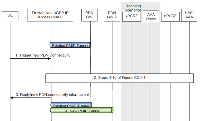
Figure 6.8.1.1-1: Additional PDN connectivity with Network-based MM mechanism over S2a for non-roaming and roaming
(⇒ copy of original 3GPP image)
(⇒ copy of original 3GPP image)
The steps in the procedure which are marked as optional occur only if dynamic policy provisioning has been deployed.
In the roaming case, messages are forwarded between the Trusted Non-3GPP IP Access and the hPCRF via the vPCRF. In the case of LBO, messages are forwarded between the PDN-GW and the hPCRF via the vPCRF also. Further, in the case of LBO, messages between the PDN-GW and the 3GPP AAA Server are sent via the 3GPP AAA Proxy.
Step 1.
When the UE wishes to connect to an additional PDN, it sends a trigger indicating that connectivity with that specific PDN is desired. The UE provides information about the new PDN by using an APN. When multiple PDN connections to a single APN are supported then some additional access specific mechanism is needed between the UE and the MAG to differentiate the PDN connections towards the same APN. If supported by the non-3GPP access, the UE may send Protocol Configuration Options in this step using access specific mechanisms. The Protocol Configuration Options provided by the UE may include the user credentials for PDN access authorization. The UE triggers the re-establishment of existing PDN connectivity after the handover by providing a Request Type indicating "Handover" on accesses that support the indication.
Step 2.
At this step the trusted non-3GPP IP access performs PDN-GW selection as described in clause 4.5.1. Steps 4 to 10 according to clause 6.2.1 are executed with PDN-GW2 instead of PDN-GW1.
Step 3.
The trusted non-3GPP IP access system sends the reply message to the UE with the allocated IP address from the PDN that the UE indicated at step 1. If supported by the non-3GPP access, the Protocol Configuration Options provided by the PDN-GW in step 2 are returned to the UE in this step using access specific mechanisms. Since UE requested for additional PDN connectivity, the UE configures the IP address received from the MAG without deleting its configuration for connectivity with any other previously established PDN. For handover, the UE is returned the IP address the UE obtained before the handover during PDN connectivity establishment.
Step 4.
The PMIPv6 tunnel is thus set up between the Trusted Non-3GPP IP Access and the PDN-GW corresponding to the requested additional PDN while maintaining tunnels previously established for other PDNs.
6.8.1.2 Chained PMIP-based S8-S2a Roaming Case p. 144
This clause defines the UE-initiated Connectivity to Additional PDN for PMIP-based S8-S2a chaining. This procedure also applies for PMIP-based S8-S2b chaining.
Multiple PDN connections to a single APN can be established if it is supported by the MAG, the Serving-GW and the PDN-GW. When multiple PDN connections to a single APN are supported, during the establishment of a new PDN connection, the use of PDN connection identity is used as specified in clause 6.8.1.1 and the Serving-GW shall forward the PDN connection identity between the concatenated PMIP tunnels.

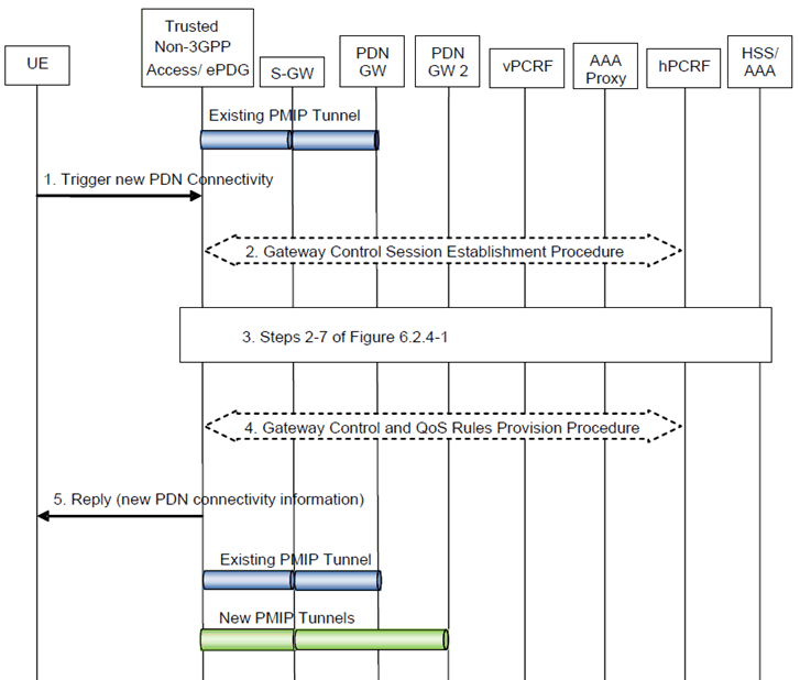
Figure 6.8.1.2-1: Additional PDN connectivity for chained PMIP-based S8-S2a/b roaming scenarios
(⇒ copy of original 3GPP image)
(⇒ copy of original 3GPP image)
The optional interaction steps between the gateways and the PCRF in the procedures only occur if dynamic policy provisioning is deployed. Otherwise policy may be statically configured with the gateway.
The gateway control signalling in steps 2 and 4 between the gateway and PCRF occur only for Trusted Non-3GPP IP Accesses.
Step 1.
When the UE wishes to connect to an additional PDN, it sends a trigger according to step 1 of clause 6.8.1.1 (Figure 6.8.1.1-1).
Step 2.
The non-3GPP access gateway initiates the Gateway Control Session Establishment Procedure with the hPCRF by way of the vPCRF, as specified in TS 23.203.
Step 3.
Steps 2 to 7 according to clause 6.2.4 (Figure 6.2.4-1) are executed with PDN-GW2 instead of PDN-GW1.
Step 4.
In case the QoS rules have changed, the hPCRF by way of the vPCRF updates the QoS rules at the non-3GPP access gateway by initiating the GW Control Session Modification Procedure, as specified in TS 23.203.
Step 5.
The trusted non-3GPP access system or ePDG sends the reply message to the UE according to step 3 of clause 6.8.1.1 (Figure 6.8.1.1-1). If supported by the trusted non-3GPP access system, the Protocol Configuration Option provided by the PDN-GW in step 3 are returned to the UE in this step using access specific mechanisms.
6.8.2 UE-initiated Connectivity to Additional PDN with MIPv4 FACoA on S2a p. 145
This procedure is used to request for connectivity to an additional PDN over trusted non-3GPP access with MIPv4 FACoA on S2a when the UE already has active PDN connections over such trusted access. This procedure is also used to request for connectivity to an additional PDN over trusted non-3GPP access with MIPv4 FACoA on S2a when the UE is simultaneously connected to such trusted access and a 3GPP access, and the UE already has active PDN connections over both the accesses.
Multiple connections to the same APN is supported for MIPv4 FACoA on S2a as the UE and PDN-GW distinguish between connections by means of the UE's distinct home addresses for each connection.

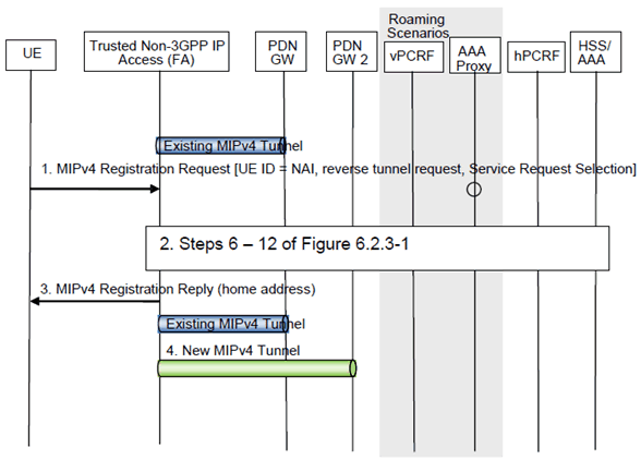
Figure 6.8.2-1: UE-initiated Connectivity to Additional PDN with MIPv4 FACoA on S2a
(⇒ copy of original 3GPP image)
(⇒ copy of original 3GPP image)
This procedure applies to the Non-Roaming (Figure 4.2.2-1), Roaming (Figure 4.2.3-1) and Local Breakout (Figure 4.2.3-4) cases. For the Roaming and Local Breakout cases, the vPCRF forwards messages between the non-3GPP access and the hPCRF. In the Local Breakout case, the vPCRF forwards messages between the PDN-GW and the hPCRF. In the Roaming and LBO cases, the 3GPP AAA Proxy serves as an intermediary between the Trusted Non-3GPP IP Access and the 3GPP AAA Server in the HPLMN. In the non-roaming case, the vPCRF is not involved at all.
Step 1.
When the UE wishes to connect to an additional PDN, UE sends a Registration Request (RRQ) (MN-NAI, lifetime, APN) RFC 5944 message to the FA as specified in RFC 5944. Reverse Tunnelling shall be requested. This ensures that all traffic will go through the PDN-GW. The RRQ message shall include the NAI-Extension RFC 2794. The UE may not indicate a specific Home Agent address in the RRQ message, in which case the PDN Gateway/Home Agent is selected by the FA. The UE then receives the IP address of the PDN Gateway in step 3 as part of the Registration Reply (RRP) message. The UE should then include the PDN Gateway address in the Home Agent address field of subsequent RRQ messages. The UE provides information about the new PDN by using an APN as specified in RFC 5446.
Step 2.
The trusted non-3GPP IP access performs a PDN-GW selection for the new PDN connection. Steps 6-12 of clause 6.2.3 are executed with PDN-GW2 instead of PDN-GW1. The AAA interactions for obtaining Authentication and Authorization information occur irrespective of whether the UE has a PDN connection with a different APN to the same PDN-GW or not.
Step 3.
The FA processes the RRP (MN-NAI, Home Address, Home Agent Address, APN) message according to RFC 5944 and sends a corresponding RRP message to the UE.
Step 4.
The MIPv4 tunnel is thus set up between the Trusted Non-3GPP IP Access and the PDN-GW2 corresponding to the requested additional PDN while maintaining tunnels previously established for other PDNs.
6.8.3 UE-initiated Connectivity to Additional PDN from Trusted Non-3GPP IP Access with DSMIPv6 on S2c p. 146
This clause is related to the case when the UE attaches to a Trusted Non-3GPP Access network and host-based mobility management mechanisms are used. Dual Stack MIPv6, RFC 5555 is used for supporting mobility over S2c interface. This case describes the scenario when UE adds connectivity to one or more additional PDN at any time after initial attach. Since host-based mobility mechanisms are used, the procedure is similar to the initial attach procedure.
This procedure is also used to request for connectivity to an additional PDN over trusted non-3GPP access with DSMIPv6 on S2c when the UE is simultaneously connected to such trusted access and a 3GPP access, and the UE already has active PDN connections over both the accesses.

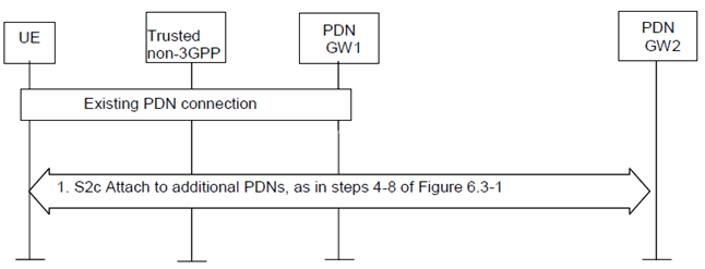
Figure 6.8.3-1: UE-initiated connectivity to multiple PDNs from Trusted Non-3GPP IP Access with DSMIPv6
(⇒ copy of original 3GPP image)
(⇒ copy of original 3GPP image)
When the initial attachment is performed, the UE performs procedures described in clause 6.3, Figure 6.3-1, to obtain connectivity with a PDN-GW and a specific PDN. If at any time, the UE wants to obtain connectivity with additional PDNs, it repeats steps 4-8 of Figure 6.3-1.
Step 1.
If the UE discovers a different PDN-GW for the additional PDN connectivity, when the current PDN-GW could provide access to the additional PDN, the PDN-GW reallocation procedure may be used, as defined in clause 6.10.
The UE performs PDN-GW discovery for the new PDN and repeats steps 4-8 of clause 6.3, Figure 6.3-1 for each additional PDN the UE wants to connect to. This step can be performed and be repeated at any time after the initial attach for one or multiple PDNs.