Content for TS 23.402 Word version: 18.3.0
0…
4…
4.2…
4.2.2
4.2.3
4.3…
4.4…
4.5…
4.5.7…
4.6…
4.7…
4.7.2…
4.8…
4.8.2a…
4.9…
5…
5.2…
5.4…
5.5
5.6…
5.7…
5.8…
6…
6.2…
6.3
6.4…
6.4.3…
6.5…
6.6…
6.7…
6.8…
6.10…
6.13…
6.15…
7…
7.2…
7.3
7.4…
7.5…
7.6…
7.8…
7.10…
8…
8.2.1.2
8.2.1.3…
8.2.2
8.2.3…
8.2.6…
8.3…
8.4…
8.5…
9…
9.3…
9.4…
10…
13…
16…
16.1.2…
16.1.6…
16.2…
16.2.1a…
16.3…
16.4…
16.7…
16.8…
16.10…
17…
A…
C…
E…
E Gateway Relocation in the Trusted Non-3GPP IP Access
E.1 Gateway Relocation with PMIPv6 on S2a
E.2 Gateway Relocation with MIPv4 FACoA on S2a
F Deployment of Non-3GPP Trusted WLAN Access on S2a
$ Change History
E Gateway Relocation in the Trusted Non-3GPP IP Access p. 310
Gateway relocation within the Trusted Non-3GPP IP Access is possible using the procedures defined in this clause. The trigger for gateway relocation and any mechanisms for preserving or transferring context between gateways within the Trusted Non-3GPP IP Access is considered out of scope of this specification and should be handled within standards external to 3GPP.
In both the case of PMIPv6 and MIP v4 FACoA on S2a, the Gateway Control Session for the target gateway of the relocation is established before the intra-non-3GPP handover occurs. After the handover, the Gateway Control Session in the source gateway of the handover is terminated.
The mobility management and policy control signalling are both shown as optional messages. This is to allow flexibility depending on the requirements of the trusted non-3GPP IP access system. This allows a policy control signalling relocation (on Gxa) or a relocation of the local mobility anchor (S2a) or both (Gxa and S2a).
E.1 Gateway Relocation with PMIPv6 on S2a p. 310

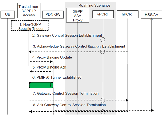
Figure E.1-1: Gateway Relocation when PMIPv6 MM mechanism is used over S2a
(⇒ copy of original 3GPP image)
(⇒ copy of original 3GPP image)
When the Gateway Relocation procedure occurs in the Non-Roaming case (Figure 4.2.2-1), the vPCRF is not involved.
In the case of Roaming (Figure 4.2.3-1) and Local Breakout (Figure 4.2.3-4), the vPCRF is employed to forward messages from the hPCRF in the home PLMN, by way of the vPCRF in the VPLMN to the non-3GPP access.
Step 1.
A gateway relocation is triggered, to be initiated by the Trusted Non-3GPP IP Access. These trigger is outside the scope of 3GPP standardization.
Step 2.
The target Gateway in the Trusted Non-3GPP IP Access sends a Gateway Control Session Establishment message to the hPCRF.
Step 3.
The PCRF responds to the target Gateway an Ack Gateway Control Session Establishment (QoS Rules, Event Triggers) message. The PCC rules provide the PDN-GW with information required to enforce the dedicated bearer policy. The event triggers indicate to the PDN-GW when to report an event back to the PCRF related to the dedicated bearer.
Step 4.
The target Gateway sends a Proxy Binding Update (MN NAI) message to the PDN-GW to register the UE at the PDN-GW. The MN NAI identifies the UE.
Step 5.
After creating the binding cache entry for the UE, the PDN-GW responds with a Proxy Binding Acknowledgement (MN NAI, Lifetime, UE Address Info) message to the MAG. The MN NAI repeats the UE identity sent previously. The Lifetime expresses the duration of validity of the binding. The UE Address info includes the allocated IP Address(es) corresponding to the IP-CAN session.
Step 6.
The PMIP tunnel from the target gateway to the PDN-GW is established.
Step 7.
The source Gateway in the Trusted Non-3GPP IP Access system sends a Gateway Control Session Termination to the PCRF. This gateway ceases to perform Bearer Binding and associated policy controlled functions.
Step 8.
The PCRF sends an Acknowledge Gateway Control Session Termination message to the Trusted Non-3GPP IP Access acknowledging the termination of the control session.
E.2 Gateway Relocation with MIPv4 FACoA on S2a p. 311

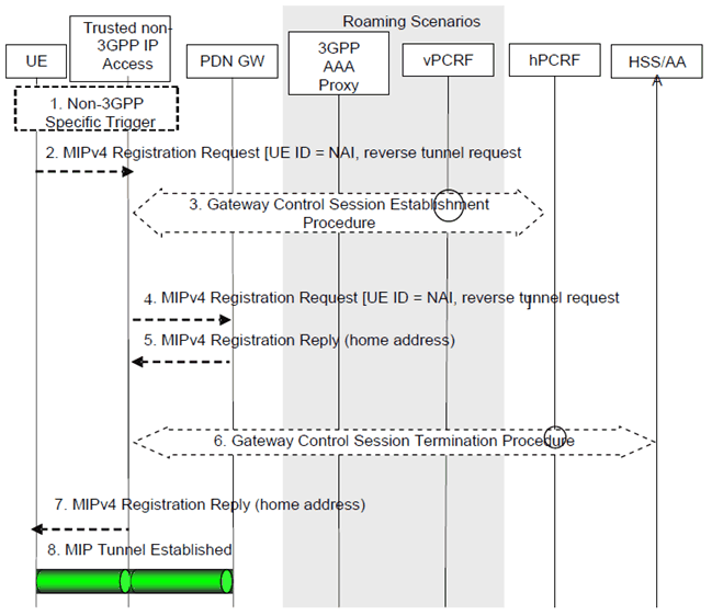
Figure E.2-1: Gateway Relocation when MIPv4 FACoA mode MM mechanism is used over S2a
(⇒ copy of original 3GPP image)
(⇒ copy of original 3GPP image)
When the Gateway Relocation procedure occurs in the Non-Roaming case (Figure 4.2.2-1), the vPCRF is not involved.
In the case of Roaming (Figure 4.2.3-1) and Local Breakout (Figure 4.2.3-4), the vPCRF is employed to forward messages from the hPCRF in the home PLMN, by way of the vPCRF in the VPLMN to the non-3GPP access.
Step 1.
A gateway relocation is triggered, to be initiated by the UE. This trigger is outside the scope of 3GPP standardization.
Step 2.
The UE sends a Registration Request (RRQ) RFC 5944 message to the FA. Reverse Tunnelling shall be requested. This ensures that all traffic will go through the PDN-GW. The RRQ message shall include the NAI-Extension RFC 2794 [34] and the Home Agent Address.
Step 3.
The Trusted non-3GPP access initiates the Gateway Control Session Establishment Procedure with the PCRF, as specified in TS 23.203. The Trusted non-3GPP access provides the information to the PCRF to correctly associate it with the IP-CAN session to be established in Step 9 and also to convey subscription related parameters to the PCRF.
Step 4.
The FA processes the message according to RFC 5944 and forwards a corresponding RRQ message to the PDN-GW.
Step 5.
The PDN-GW allocates an IP address for the UE and sends a Registration Reply (RRP) RFC 5944 [12] to the FA, including the IP address allocated for the UE.
Step 6.
The Trusted Non-3GPP Access Network initiates the Gateway Control Session Termination Procedure with the PCRF as specified in TS 23.203. The Trusted Non-3GPP Access Network no longer applies QoS policy to service data flows for this UE.
Step 7.
The FA processes the RRP according to RFC 5944 and sends a corresponding RRP message to the UE.
Step 8.
IP connectivity from the UE to the PDN-GW is now setup. A MIP tunnel is established between the FA in the Trusted Non-3GPP IP Access and the PDN-GW.
F Deployment of Non-3GPP Trusted WLAN Access on S2a |R11| p. 313
WLAN networks may be deployed such that separate SSIDs are used for EPC-routed and non-seamless WLAN offload, e.g. <ssid_a> and <ssid_b>.
WLAN networks may also be deployed such that the same SSID in a WLAN Access Point provides different type of network access to different users attached to this Access Point. For example, a given SSID <ssid_x> may provide EPC-routed access for subscriber A and only allow non-seamless WLAN offload for subscriber B. In such a deployment it is up to the operator to provide network configuration that supports different user access preferences, subscriptions and UE configurations.
It is recommended that the UE can be configured to apply different behavior when connected to different SSIDs, e.g. allow or prevent the usage of certain applications on specific SSIDs. For example, for the SSIDs used for EPC access through S2a over Trusted WLAN, the UE can be configured to disable applications that require local connectivity (e.g. DLNA applications) and enable applications that require EPC connectivity to the default APN used for access through S2a over Trusted WLAN. Such kind of special behavior for SSIDs used for EPC access through S2a over Trusted WLAN can improve the user experience and prolong the UE battery life.