Content for TS 23.402 Word version: 18.3.0
0…
4…
4.2…
4.2.2
4.2.3
4.3…
4.4…
4.5…
4.5.7…
4.6…
4.7…
4.7.2…
4.8…
4.8.2a…
4.9…
5…
5.2…
5.4…
5.5
5.6…
5.7…
5.8…
6…
6.2…
6.3
6.4…
6.4.3…
6.5…
6.6…
6.7…
6.8…
6.10…
6.13…
6.15…
7…
7.2…
7.3
7.4…
7.5…
7.6…
7.8…
7.10…
8…
8.2.1.2
8.2.1.3…
8.2.2
8.2.3…
8.2.6…
8.3…
8.4…
8.5…
9…
9.3…
9.4…
10…
13…
16…
16.1.2…
16.1.6…
16.2…
16.2.1a…
16.3…
16.4…
16.7…
16.8…
16.10…
17…
A…
C…
E…
8.3 Handover from 3GPP access to Trusted Non-3GPP IP Access with MIPv4 FACoA on S2a
8.3b Handover from Trusted Non-3GPP IP Access with MIPv4 FACoA on S2a to 3GPP access
...
...
8.3 Handover from 3GPP access to Trusted Non-3GPP IP Access with MIPv4 FACoA on S2a p. 208

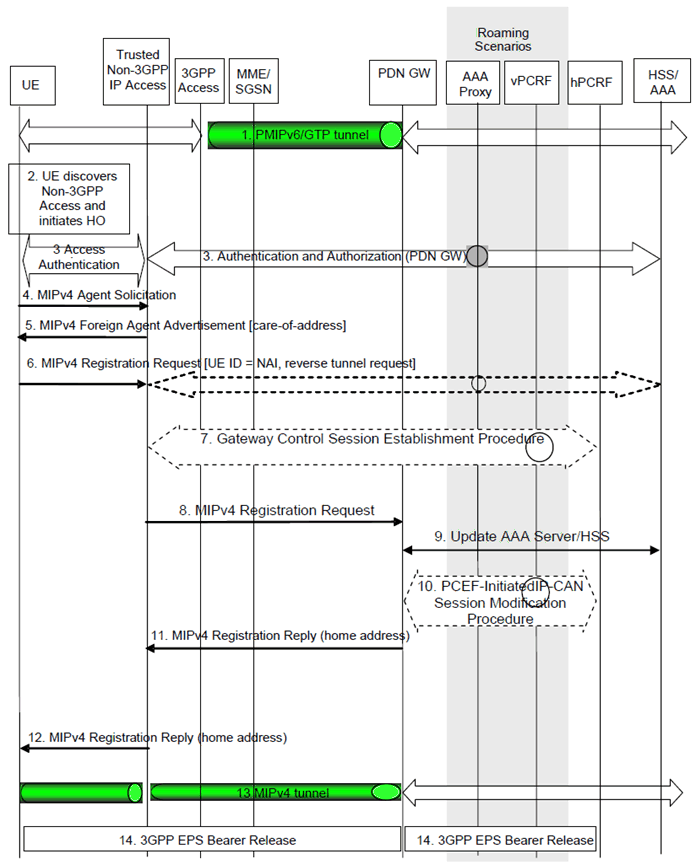
Figure 8.3-1: 3GPP IP Access to Non-3GPP IP access Handover over MIPv4-based S2a
(⇒ copy of original 3GPP image)
(⇒ copy of original 3GPP image)
In case of connectivity to multiple PDNs the following applies:
- If the UE is connected to both 3GPP access and trusted non-3GPP access before the handover of PDN connections to trusted non-3GPP access is triggered, steps 2 to 5 shall be skipped.
- If the UE is connected only to 3GPP access before the handover of PDN connections to trusted non-3GPP access is triggered, steps 2 to 5 shall be performed.
- Steps 6 to 14 shall be repeated for each PDN connection that is being transferred from 3GPP access.
Step 1.
The UE is connected in the 3GPP Access and has a PMIPv6 or GTP tunnel on the S5 interface.
Step 2.
The UE discovers the trusted non-3GPP IP access system and determines to transfer its current sessions (i.e. handover) from the currently used 3GPP Access to the discovered trusted non-3GPP IP access system. The mechanisms that aid the UE to discover the trusted non-3GPP IP access system, are specified in clause 4.8 (Network Discovery and Selection).
Step 3.
The UE performs access authentication and authorization in the non-3GPP access system as defined by TS 33.402. The 3GPP AAA server authenticates and authorizes the UE for access in the trusted non-3GPP system. As part of the authentication and authorization procedure, the 3GPP AAA server obtains the PDN-GW identity from the HSS and it returns the same PDN-GW identity to the trusted non-3GPP access system at this step (upon successful authentication and authorization).
Step 4.
The UE may send an Agent Solicitation (AS) RFC 5944 message. Specification of this message is out of the scope of 3GPP.
Step 5.
The FA in the Trusted Non-3GPP IP Access sends a Foreign Agent Advertisement (FAA) (RFC 5944) message to the UE. The FAA message includes the Care-of Address (CoA) of the Foreign Agent function in the FA. Specification of this message is out of the scope of 3GPP.
Step 6.
The UE sends a Registration Request (RRQ) (MN-NAI, lifetime) message as defined in RFC 5944 to the FA as specified in RFC 5944. Reverse Tunnelling shall be requested. This ensures that all traffic will go through the PDN-GW. The RRQ message shall include the NAI-Extension RFC 2794. The UE may not indicate a specific Home Agent address in the RRQ message, in which case the FA uses the PDN-GW address as received in step 3. The UE then receives the IP address of the PDN Gateway in step 11 as part of the RRP message. The UE should then include the PDN Gateway address in the Home Agent address field of subsequent RRQ messages.
Step 7.
The Trusted non-3GPP access initiates the Gateway Control Session Establishment Procedure with the PCRF. The Trusted non-3GPP access provides the information to the PCRF to correctly associate it with the IP-CAN session and also to convey subscription related parameters to the PCRF. If the Trusted Non-3GPP access supports UE/NW bearer control mode, the PCRF provides all the QoS rules required for the Trusted Non-3GPP access to perform the bearer binding.
Step 8.
The FA processes the message according to RFC 5944 and forwards a corresponding RRQ (MN-NAI, lifetime) message to the PDN-GW.
Step 9.
The PDN-GW informs the 3GPP AAA Server of its PDN-GW identity and the APN corresponding to the UE's PDN Connection and obtains authentication and authorization information from the 3GPP AAA Server. The message includes information that identifies the PLMN in which the PDN-GW is located. The 3GPP AAA Server may update the information registered in the HSS as described in clause 12.
Step 10.
The PDN-GW allocates an IP address for the UE. The PDN-GW initiates the IP-CAN Session Modification Procedure with the PCRF, as specified in TS 23.203. The PDN-GW provides information to the PCRF that the IP-CAN type has changed and the PCRF responds to the PDN-GW with PCC rules and event triggers.
Step 11.
The PDN-GW sends a Registration Reply (RRP) (MN-NAI, Home Address, Home Agent Address) message as defined in RFC 5944 to the FA.
Step 12.
The FA processes the RRP (MN-NAI, Home Address) according to RFC 5944 and sends a corresponding RRP message to the UE.
Step 13.
IP connectivity from the UE to the PDN-GW is now setup. A MIP tunnel is established between the FA in the Trusted Non-3GPP IP Access and the PDN-GW.
Step 14.
The PDN-GW shall initiate the PDN-GW Initiated PDN Disconnection procedure in 3GPP access as defined in clause 5.6.2.2 or the PDN-GW Initiated Bearer Deactivation procedure as defined in clause 5.4.4.1 of TS 23.401.
8.3b Handover from Trusted Non-3GPP IP Access with MIPv4 FACoA on S2a to 3GPP access |R10| p. 210
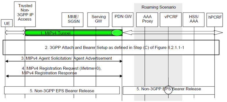
In this scenario, the session starts in a trusted non-3GPP access system using MIPv4 FA CoA and subsequently, the session hands over to a 3GPP access system. The steps involved are shown in the figure below.

Figure 8.3b-1: Handover from Trusted Non-3GPP IP Access with MIPv4 FACoA on S2a to 3GPP Access
(⇒ copy of original 3GPP image)
(⇒ copy of original 3GPP image)
For connectivity to multiple PDNs the following applies:
- If UE is connected to both 3GPP access and non-3GPP access before the handover of PDN connections to 3GPP access is triggered, steps 2 to 16 of Figure 8.2.1.1-1 shall be skipped and the UE shall only perform step 17 of Figure 8.2.1.1-1 for each PDN connection that is being transferred from non-3GPP access.
- If UE is connected only to non-3GPP access before the handover of PDN connections to 3GPP access is triggered, steps 2 to 16 of Figure 8.2.1.1-1 shall be performed. In step 3 of Figure 8.2.1.1-1 the UE shall provide the APN corresponding to one of the PDN connections that are being transferred from non-3GPP access. The UE shall then repeat step 17 of Figure 8.2.1.1-1 for each of the remaining PDN connections that are being transferred from non-3GPP access.
- Steps 4 and 5 of Figure 8.3b-1 shall be repeated for each PDN connection that is being transferred from non-3GPP access.
Step 1.
The UE uses a trusted non-3GPP access system. It has a MIPv4 session with the PDN-GW with a FA in the trusted non-3GPP access using FACoA.
Step 2.
The UE discovers and attaches to the 3GPP access as defined in Step (C) of Figure 8.2.1.1-1, except that the IP-CAN session modification and the path switch are triggered as explained below.
Step 3.
The UE may send an Agent Solicitation RFC 5944 message. The HA functionality in the PDN-GW sends an Agent Advertisement (AA) RFC 5944 message to the UE.
Step 4.
The UE determines that it is back home through inspection of the H bit and advertised prefix within the agent advertisement (AA) received in the previous step. The UE sends a Registration Request message with the destination address set to the HA's address and with a Lifetime field set to 0 to indicate deregistration. Once the deregistration request is accepted, the UE receives an Registration Response message from the HA.
Step 5.
The PDN-GW shall initiate resource allocation deactivation procedure in the trusted/untrusted non-3GPP IP access as defined in clause 6.12.