Content for TS 38.423 Word version: 17.3.0
8.4.4 Reset
8.4.5 Error Indication
8.4.6 Xn Removal
8.4.7 Failure Indication
8.4.8 Handover Report
8.4.9 Mobility Settings Change
8.4.10 Resource Status Reporting Initiation
8.4.11 Resource Status Reporting
8.4.12 Access And Mobility Indication
8.5 IAB Procedures
8.5.1 F1-C Traffic Transfer
8.5.2 IAB Transport Migration Management
8.5.3 IAB Transport Migration Modification
8.5.4 IAB Resource Coordination
...
...
8.4.4 Reset p. 93
8.4.4.1 General p. 93
The purpose of the Reset procedure is to align the resources in the NG-RAN node1 and the NG-RAN node2 in the event of an abnormal failure. The procedure either resets the Xn interface or selected UE contexts. This procedure doesn't affect the application level configuration data exchanged during, e.g., the Xn Setup procedure.
The procedure uses non UE-associated signalling.
8.4.4.2 Successful Operation p. 94
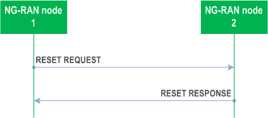
The procedure is initiated with the RESET REQUEST message sent from the NG-RAN node1 to the NG-RAN node2. Upon receipt of this message,
If the RESET REQUEST message indicates full reset, the NG-RAN node2 shall abort any other ongoing procedure (except for a Reset procedures).
If the RESET REQUEST message indicates partial reset, the NG-RAN node2 shall abort any other ongoing procedure (except for a Reset procedures) on the same Xn interface related to a UE associated signalling connection indicated in the RESET REQUEST message.
- if the RESET REQUEST message indicates full reset the NG-RAN node2 shall abort any other ongoing procedures over Xn between the NG-RAN node1 and the NG-RAN node2. The NG-RAN node2 shall delete all the context information related to the NG-RAN node1, except the application level configuration data exchanged during the Xn Setup or the NG-RAN node Configuration Update procedures and release the corresponding resources. After completion of release of the resources, the NG-RAN node2 shall respond with the RESET RESPONSE message.
- if the RESET REQUEST message indicates partial reset, the NG-RAN node2 shall abort any other ongoing procedures only for the indicated UE associated signalling connections identified either by the NG-RAN node1 UE XnAP ID IE or the NG-RAN node1 UE XnAP ID IE or both, for which the NG-RAN node2 shall delete all the context information related to the NG-RAN node1 and release the corresponding resources. After completion of release of the resources, the NG-RAN node2 shall respond with the RESET RESPONSE message indicating the UE contexts admitted to be released. The NG-RAN node2 receiving the request for partial reset does not need to wait for the release or reconfiguration of radio resources to be completed before returning the RESET RESPONSE message. The NG-RAN node2 receiving the request for partial reset shall include in the RESET RESPONSE message, for each UE association to be released, the same list of UE-associated logical Xn-connections over Xn. The list shall be in the same order as received in the RESET REQUEST message and shall include also unknown UE-associated logical Xn-connections.
8.4.4.3 Unsuccessful Operation p. 94
Void.
8.4.4.4 Abnormal Conditions p. 94
If the RESET REQUEST message is received, any other ongoing procedure (except another Reset procedure) on the same Xn interface shall be aborted.
If the Reset procedure is ongoing and the responding node receives the RESET REQUEST message from the peer entity on the same Xn interface, it shall respond with the RESET RESPONSE message as specified in clause 8.4.4.2.
If the initiating node does not receive the RESET RESPONSE message, the initiating node may reinitiate the Reset procedure towards the same NG-RAN node, provided that the content of the new RESET REQUEST message is identical to the content of the previously unacknowledged RESET REQUEST message.
8.4.5 Error Indication p. 95
8.4.5.1 General p. 95
The Error Indication procedure is initiated by an NG-RAN node to report detected errors in one incoming message, provided they cannot be reported by an appropriate failure message.
If the error situation arises due to reception of a message utilising UE associated signalling, then the Error Indication procedure uses UE-associated signalling. Otherwise the procedure uses non UE-associated signalling.
8.4.5.2 Successful Operation p. 95
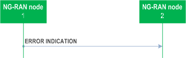
When the conditions defined in clause 10 are fulfilled, the Error Indication procedure is initiated by the ERROR INDICATION message sent from the node detecting the error situation.
The ERROR INDICATION message shall contain at least either the Cause IE or the Criticality Diagnostics IE.
In case the Error Indication procedure is triggered by UE associated signalling, in the course of handover signalling and signalling for dual connectivity, the Old NG-RAN node UE XnAP ID IE and the New NG-RAN node UE XnAP ID IE shall be included in the ERROR INDICATION message. If any of the Old NG-RAN node UE XnAP ID IE and the New NG-RAN node UE XnAP ID IE is not correct, the cause shall be set to an appropriate value.
If case of network sharing with multiple cell ID broadcast with shared Xn-C signalling transport, as specified in TS 38.300, the ERROR INDICATION message shall include the Interface Instance Indication IE to identify the corresponding interface instance.
8.4.5.3 Unsuccessful Operation p. 95
Not applicable.
8.4.5.4 Abnormal Conditions p. 95
Void.
8.4.6 Xn Removal p. 95
8.4.6.1 General p. 95
The purpose of the Xn Removal procedure is to remove the interface instance between two NG-RAN nodes in a controlled manner. If successful, this procedure erases any existing application level configuration data in the two nodes.
The procedure uses non UE-associated signaling.
8.4.6.2 Successful Operation p. 96
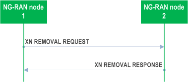
An NG-RAN node1 initiates the procedure by sending the XN REMOVAL REQUEST message to a candidate NG-RAN node2. Upon reception of the XN REMOVAL REQUEST message the candidate NG-RAN node2 shall reply with the XN REMOVAL RESPONSE message. After receiving the XN REMOVAL RESPONSE message, the initiating NG-RAN node1 shall initiate removal of the TNL association towards NG-RAN node2 and may remove all resources associated with that interface instance. The candidate NG-RAN node2 may then remove all resources associated with that interface instance.
If the Xn Removal Threshold IE is included in the XN REMOVAL REQUEST message, the candidate NG-RAN node2 shall, if supported, accept to remove the interface instance with NG-RAN node1 if the Xn Benefit Value of the interface instance determined at the candidate NG-RAN node2 is lower than the value of the Xn Removal Threshold IE.
If case of network sharing with multiple cell ID broadcast with shared Xn-C signalling transport, as specified in TS 38.300, the XN REMOVAL REQUEST message and the XN REMOVAL RESPONSE message shall include the Interface Instance Indication IE to identify the corresponding interface instance.
8.4.6.3 Unsuccessful Operation p. 96
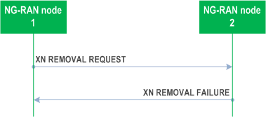
If the candidate NG-RAN node2 cannot accept to remove the interface instance with NG-RAN node1 it shall respond with an XN REMOVAL FAILURE message with an appropriate cause value.
If case of network sharing with multiple cell ID broadcast with shared Xn-C signalling transport, as specified in TS 38.300, the XN REMOVAL REQUEST message and the XN REMOVAL FAILURE message shall include the Interface Instance Indication IE to identify the corresponding interface instance.
8.4.6.4 Abnormal Conditions p. 96
Void.
8.4.7 Failure Indication |R16| p. 97
8.4.7.1 General p. 97
The purpose of the Failure Indication procedure is to transfer information regarding RRC re-establishment attempts, or received RLF Reports, between NG-RAN nodes. The signalling takes place from the NG-RAN node at which a re-establishment attempt is made, or an RLF Report is received, to an NG-RAN node to which the UE concerned may have previously been attached prior to the connection failure. This may aid the detection of radio link failure, handover failure cases.
The procedure uses non UE-associated signalling.
8.4.7.2 Successful Operation p. 97
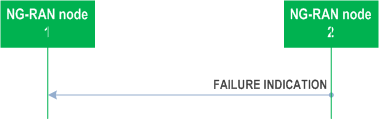
NG-RAN node2 initiates the procedure by sending the FAILURE INDICATION message to NG-RAN node1, following a re-establishment attempt or an RLF Report reception from a UE at NG-RAN node2, when NG-RAN node2 considers that the UE may have previously suffered a connection failure at a cell controlled by NG-RAN node1.
If the UE RLF Report Container IE is included in the FAILURE INDICATION message, NG-RAN node1 shall use it to derive failure case information.
8.4.7.3 Unsuccessful Operation p. 97
Not applicable.
8.4.7.4 Abnormal Conditions p. 97
Void.
8.4.8 Handover Report |R16| p. 97
8.4.8.1 General p. 97
The purpose of the Handover Report procedure is to transfer mobility related information between NG-RAN nodes.
The procedure uses non UE-associated signalling.
8.4.8.2 Successful Operation p. 98

NG-RAN node1 initiates the procedure by sending the HANDOVER REPORT message to NG-RAN node2. When receiving the message NG-RAN node2 shall assume that a mobility-related problem was detected.
If the Handover Report Type IE is set to "HO too early" or "HO to wrong cell", then NG-RAN node1 indicates to NG-RAN node2 that, following a successful handover from a cell of NG-RAN node2 to a cell of NG-RAN node1, a radio link failure occurred and the UE attempted RRC Re-establishment or re-connected either at the original cell of NG-RAN node2 (Handover Too Early), or at another cell (Handover to Wrong Cell). The detection of Handover Too Early and Handover to Wrong Cell events is made according to TS 38.300.
The HANDOVER REPORT message may include:
If NG-RAN node1 receives a UE RLF Report from an NG-RAN node via the FAILURE INDICATION message, as described in TS 38.300, NG-RAN node1 may also include it in the UE RLF Report Container IE included in the HANDOVER REPORT message.
- the Mobility Information IE, if the Mobility Information IE was sent for this handover from NG-RAN node2 (in case the NG-RAN node2 provided it more than once, the most recent Mobility Information IE is included in the HANDOVER REPORT message);
- the Source cell C-RNTI IE.
- the CHO Configuration IE, if the CHO Configuration IE was sent for this handover from NG-RAN node2.
8.4.8.3 Unsuccessful Operation p. 98
Not applicable.
8.4.8.4 Abnormal Conditions p. 98
Void.
8.4.9 Mobility Settings Change |R16| p. 98
8.4.9.1 General p. 98
This procedure enables an NG-RAN node to negotiate the handover trigger settings with a peer NG-RAN node controlling neighbouring cells.
The procedure uses non UE-associated signalling.
8.4.9.2 Successful Operation p. 99
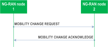
NG-RAN node1 initiates the procedure by sending the MOBILITY CHANGE REQUEST message to NG-RAN node2.
Upon receipt, NG-RAN node2 shall evaluate if the proposed NG-RAN node2 handover trigger modification may be accepted. If NG-RAN node2 is able to successfully complete the request it shall reply with MOBILITY CHANGE ACKNOWLEDGE message.
If the NG-RAN node1 SSB Offsets IE is included in the MOBILITY CHANGE REQUEST, the NG-RAN node2 should take into account the value of SSB Offset IE for UE measurements received for the SSB Area indicated by the SSB Index IE.
If the NG-RAN node2 Proposed SSB Offsets IE is included in the MOBILITY CHANGE REQUEST, the NG-RAN node2 shall, if supported, evaluate if the proposed value of SSB Offset IE may be accepted for the SSB Area indicated by the SSB Index IE. If NG-RAN node2 is able to successfully complete the request it shall reply with MOBILITY CHANGE ACKNOWLEDGE message.
8.4.9.3 Unsuccessful Operation p. 99
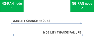
If the requested parameter modification is refused by NG-RAN node2, or if NG-RAN node2 is not able to complete the procedure, NG-RAN node2 shall send the MOBILITY CHANGE FAILURE message with the Cause IE set to an appropriate value. NG-RAN node2 may include the Mobility Parameters Modification Range IE in the MOBILITY CHANGE FAILURE message, for example in cases when the proposed change is out of the permitted range.
NG-RAN node2 may include the SSB Offset Modification Range IE in the MOBILITY CHANGE FAILURE message, for example in cases when the proposed change is out of the permitted range.
8.4.9.4 Abnormal Conditions p. 99
Void.
8.4.10 Resource Status Reporting Initiation |R16| p. 100
8.4.10.1 General p. 100
This procedure is used by an NG-RAN node to request the reporting of load measurements to another NG-RAN node.
The procedure uses non UE-associated signalling.
8.4.10.2 Successful Operation p. 100
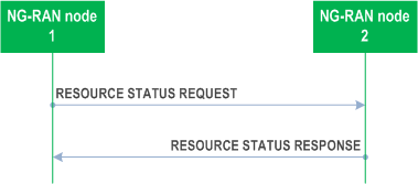
NG-RAN node1 initiates the procedure by sending the RESOURCE STATUS REQUEST message to NG-RAN node2 to start a measurement, stop a measurement or add cells to report for a measurement. Upon receipt, NG-RAN node2:
When starting a measurement, the Report Characteristics IE in the RESOURCE STATUS REQUEST indicates the type of objects NG-RAN node2 shall perform measurements on. For each cell, NG-RAN node2 shall include in the RESOURCE STATUS UPDATE message:
- shall initiate the requested measurement according to the parameters given in the request in case the Registration Request IE set to "start"; or
- shall stop all cells measurements and terminate the reporting in case the Registration Request IE is set to "stop"; or
- shall add cells indicated in the Cell To Report List IE to the measurements initiated before for the given measurement IDs, in case the Registration Request IE is set to "add". If measurements are already initiated for a cell indicated in the Cell To Report List IE, this information shall be ignored.
- the Radio Resource Status IE, if the first bit, "PRB Periodic" of the Report Characteristics IE included in the RESOURCE STATUS REQUEST message is set to "1". If NG-RAN node2 is a gNB and if the cell for which Radio Resource Status IE is requested to be reported supports more than one SSB, the Radio Resource Status IE for such cell shall include the SSB Area Radio Resource Status Item IE for all SSB areas supported by the cell. If the SSB To Report List IE is included for a cell, the Radio Resource Status IE for such cell shall include the requested SSB Area Radio Resource Status List IE; If the cell for which Radio Resource Status IE is requested to be reported supports more than one slice, and if the Slice To Report List IE is included for a cell, the Radio Resource Status IE for such cell shall, if supported, include the requested Slice Radio Resource Status Item IE;
- the TNL Capacity Indicator IE, if the second bit, "TNL Capacity Ind Periodic" of the Report Characteristics IE included in the RESOURCE STATUS REQUEST message is set to "1". The received TNL Capacity Indicator IE represents the lowest TNL capacity available for the cell, only taking into account interfaces providing user plane transport.
- the Composite Available Capacity Group IE, if the third bit, "Composite Available Capacity Periodic" of the Report Characteristics IE included in the RESOURCE STATUS REQUEST message is set to "1". If the Cell Capacity Class Value IE is included within the Composite Available Capacity Group IE, this IE is used to assign weights to the available capacity indicated in the Capacity Value IE. If NG-RAN node2 is a gNB and if the cell for which Composite Available Capacity Group IE is requested to be reported supports more than one SSB, the Composite Available Capacity Group IE for such cell shall include the SSB Area Capacity Value List for all SSB areas supported by the cell, providing the SSB area capacity with respect to the Cell Capacity Class Value. If the SSB To Report List IE is included for a cell, the Composite Available Capacity Group IE for such cell shall include the requested SSB Area Capacity Value List IE. If the cell for which Composite Available Capacity Group IE is requested to be reported supports more than one slice, and if the Slice To Report List IE is included for a cell, the Slice Available Capacity IE for such cell shall include the requested Slice Available Capacity Value Downlink IE and Slice Available Capacity Value Uplink IE, providing the slice capacity with respect to the Cell Capacity Class Value.
- the Number of Active UEs IE, if the fourth bit, "Number of Active UEs Periodic" of the Report Characteristics IE included in the RESOURCE STATUS REQUEST message is set to "1";
- the RRC Connections IE, if the fifth bit, "RRC Connections Periodic" of the Report Characteristics IE included in the RESOURCE STATUS REQUEST message is set to "1".
- the NR-U Channel List IE, if the sixth bit, "NR-U Channel List Periodic" of the Report Characteristics IE included in the RESOURCE STATUS REQUEST message is set to "1".
8.4.10.3 Unsuccessful Operation p. 101
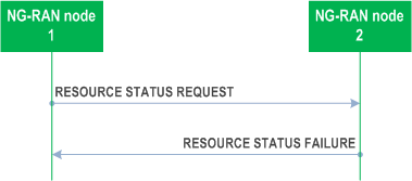
If any of the requested measurements cannot be initiated, NG-RAN node2 shall send the RESOURCE STATUS FAILURE message with an appropriate cause value.
8.4.10.4 Abnormal Conditions p. 101
For the same Measurement ID, if the initiating NG-RAN node1 does not receive either the RESOURCE STATUS RESPONSE message or the RESOURCE STATUS FAILURE message, the NG-RAN node1 may reinitiate the Resource Status Reporting Initiation procedure towards the same NG-RAN node, provided that the content of the new RESOURCE STATUS REQUEST message is identical to the content of the previously unacknowledged RESOURCE STATUS REQUEST message.
If the NG-RAN node2 receives a RESOURCE STATUS REQUEST message which includes the Registration Request IE set to "add" or "stop" and if the NG-RAN node2 Measurement ID value received in the RESOURCE STATUS REQUEST message is not used, the NG-RAN node2 shall initiate RESOURCE STATUS FAILURE message with an appropriate cause value.
If the Report Characteristics IE bitmap is set to "0" (all bits are set to "0") in the RESOURCE STATUS REQUEST message then NG-RAN node2 shall initiate a RESOURCE STATUS FAILURE message with an appropriate cause value.
If the NG-RAN node2 receives a RESOURCE STATUS REQUEST message which includes the Registration Request IE set to "start" and the NG-RAN node1Measurement ID IE corresponding to an existing on-going load measurement reporting, then NG-RAN node2 shall initiate a RESOURCE STATUS FAILURE message with an appropriate cause value.
8.4.11 Resource Status Reporting |R16| p. 102
8.4.11.1 General p. 102
This procedure is initiated by an NG-RAN node to report the result of measurements admitted by the NG-RAN node following a successful Resource Status Reporting Initiation procedure.
The procedure uses non UE-associated signalling.
8.4.11.2 Successful Operation p. 102
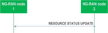
NG-RAN node2 shall report the results of the admitted measurements in RESOURCE STATUS UPDATE message. The admitted measurements are the measurements that were successfully initiated during the preceding Resource Status Reporting Initiation procedure.
If some results of the admitted measurements in RESOURCE STATUS UPDATE message are missing, NG-RAN node1 shall consider that these results were not available at NG-RAN node2.
8.4.11.3 Unsuccessful Operation p. 102
Not applicable.
8.4.11.4 Abnormal Conditions p. 102
Void
8.4.12 Access And Mobility Indication |R16| p. 102
8.4.12.1 General p. 102
The purpose of the Access and Mobility Indication procedure is to transfer Access and Mobility related information between NG-RAN nodes.
8.4.12.2 Successful Operation p. 103
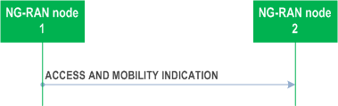
NG-RAN node1 initiates the procedure by sending the ACCESS AND MOBILITY INDICATION message sent to NG-RAN node2.
If the Successful HO Report IE is included in the ACCESS AND MOBILITY INDICATION message, NG-RAN node2 may use it to optimize handover configurations.
8.4.12.3 Abnormal Conditions p. 103
Not applicable.
8.5 IAB Procedures |R17| p. 103
8.5.1 F1-C Traffic Transfer p. 103
8.5.1.1 General p. 103
The purpose of the F1-C Traffic Transfer procedure is to deliver F1-C traffic between the M-NG-RAN node and the S-NG-RAN node serving a dual-connected IAB-node, where the F1-C traffic is either received from the IAB-node or sent to the IAB-node.
The procedure uses UE-associated signalling. This procedure is only applicable to IAB-nodes.
8.5.1.2 Successful Operation p. 103
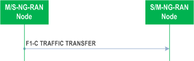
Either the M-NG-RAN Node initiates the procedure by sending the F1-C TRAFFIC TRANSFER message to the S-NG-RAN Node, or the S-NG-RAN Node initiates the procedure by sending the F1-C TRAFFIC TRANSFER message to the M-NG-RAN Node.
Upon reception of the F1-C TRAFFIC TRANSFER message, the receiving node, not being the IAB-donor of the IAB-node, shall deliver the contained F1-C traffic to the IAB-node. Alternatively, the receiving node, being the IAB-donor of the IAB-node, shall handle the received F1-C traffic as specified in TS 38.473.
8.5.1.3 Unsuccessful Operation p. 104
Not applicable.
8.5.1.4 Abnormal Conditions p. 104
Not Applicable.
8.5.2 IAB Transport Migration Management p. 104
8.5.2.1 General p. 104
The purpose of the IAB Transport Migration Management procedure is to exchange information between the F1-terminating IAB-donor and the non-F1-terminating IAB-donor of a boundary IAB-node, for the purpose of managing the migration of the boundary and descendant IAB-node traffic between the topologies managed by the two IAB-donors.
The procedure is applicable to inter-donor partial migration, inter-donor RLF recovery and inter-donor topology redundancy cases. The procedure is initiated by the F1-terminating IAB-donor of the boundary IAB-node. The procedure can be used to set up, modify and release (e.g., for the purpose of revoking) the resources under the non-F1-terminating IAB-donor used for serving the offloaded traffic.
The procedure uses UE-associated signalling.
8.5.2.2 Successful Operation p. 104
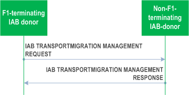
The F1-terminating IAB-donor initiates the procedure by sending the IAB TRANSPORT MIGRATION MANAGEMENT REQUEST message to the non-F1-terminating IAB-donor.
The non-F1-terminating IAB-donor may respond with the IAB TRANSPORT MIGRATION MANAGEMENT RESPONSE message by indicating:
- Traffic accepted for offloading, within the Traffic Added List IE;
- Already offloaded traffic accepted for modification, within the Traffic Modified List IE;
- Traffic not accepted for offloading, within the Traffic Not Added List IE;
- Already offloaded traffic not accepted for modification within the Traffic Not Modified List IE.
8.5.2.3 Unsuccessful Operation p. 105
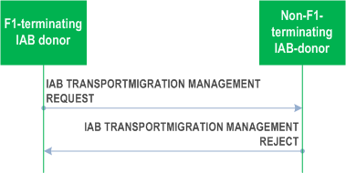
If the non-F1-terminating IAB-donor is not able to accept any traffic for offloading or modification from the F1-terminating IAB-donor, or a failure occurs during the IAB Transport Migration Management procedure, the non-F1-terminating IAB-donor sends the IAB TRANSPORT MIGRATION MANAGEMENT REJECT message with an appropriate cause value to the F1-terminating IAB-donor.
8.5.2.4 Abnormal Conditions p. 105
Not applicable.
8.5.3 IAB Transport Migration Modification p. 105
8.5.3.1 General p. 105
The purpose of the IAB Transport Migration Modification procedure is to modify the backhaul information of the offloaded traffic in the topology of the non-F1-terminating IAB-donor of a boundary IAB-node. The procedure can also be used to release the resources under the non-F1-terminating IAB-donor used for serving the offloaded traffic.
The procedure is applicable to inter-donor partial migration, inter-donor RLF recovery and inter-donor topology redundancy cases. The procedure is initiated by the non-F1-terminating IAB-donor of the boundary IAB-node.
The procedure uses UE-associated signalling.
8.5.3.2 Successful Operation p. 106
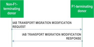
The non-F1-terminating IAB-donor initiates the procedure by sending the IAB TRANSPORT MIGRATION MODIFICATION REQUEST message to the F1-terminating IAB-donor. The F1-terminating IAB-donor responds with the IAB TRANSPORT MIGRATION MODIFICATION RESPONSE message.
If the Traffic Required To Be Modified List IE is contained in the IAB TRANSPORT MIGRATION MODIFICATION REQUEST message, the F1-terminating IAB-donor shall update the backhaul information in non-F1-terminating topology for each traffic indicated in the list, and include the Traffic Required Modified List IE in the IAB TRANSPORT MIGRATION MODIFICATION RESPONSE message.
If the Traffic To Be Released Information IE is contained in the IAB TRANSPORT MIGRATION MODIFICATION REQUEST message, the F1-terminating IAB-donor shall consider that all offloaded traffic will be released by the non-F1-terminating IAB-donor if the All Traffic Indication IE in the Traffic to Be Released Information IE is set to "true", or that only the traffic indicated by the Traffic to Be Released Item IE will be released by the non-F1-terminating IAB-donor.
If the IAB TRANSPORT MIGRATION MODIFICATION REQUEST message contains the Traffic To Be Released Information IE, the F1-terminating IAB-donor shall include the Traffic Released List IE in the IAB TRANSPORT MIGRATION MODIFICATION RESPONSE message.
If the IAB TNL Address To Be Added IE is contained in the IAB TRANSPORT MIGRATION MODIFICATION REQUEST message, the F1-terminating IAB-donor shall allocate the TNL address(es) contained in this IE to the boundary IAB-node or the descendant IAB-nodes.
If the IAB TNL Address To Be Released IE is contained in the IAB TRANSPORT MIGRATION MODIFICATION REQUEST message, the F1-terminating IAB-donor shall release the TNL address(es) contained in this IE for the boundary IAB-node or the descendant IAB-nodes.
If the IAB QoS Mapping Information IE is contained in the IAB TRANSPORT MIGRATION MODIFICATION REQUEST message, the F1-terminating IAB-donor, shall, if supported, use it to set DSCP and/or IPv6 flow label fields for the downlink IP packets of the offloaded traffic.
8.5.3.3 Unsuccessful Operation p. 106
Not applicable.
8.5.3.4 Abnormal Conditions p. 106
Not applicable.
8.5.4 IAB Resource Coordination p. 107
8.5.4.1 General p. 107
The purpose of the IAB Resource Coordination procedure is to exchange the semi-static radio resource configuration pertaining to a boundary IAB-node and/or its parent node, between the F1-terminating IAB-donor and the non-F1-terminating IAB-donor of a boundary IAB-node, for the purpose of resource multiplexing between the IAB-MT and the IAB-DU of the boundary IAB-node. The procedure can be initiated by the F1-terminating or non-F1-terminating IAB-donor of the boundary IAB-node.
The procedure uses UE-associated signalling.
8.5.4.2 Successful Operation p. 107
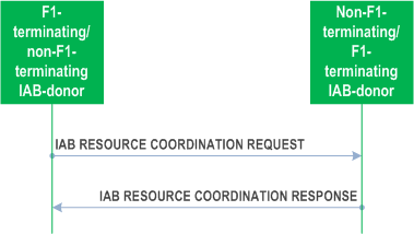
The F1-terminating/non F1-terminating IAB-donor initiates the procedure by sending the IAB RESOURCE COORDINATION REQUEST message to the non-F1-terminating/F1-terminating IAB-donor. The non-F1-terminating/F1-terminating IAB-donor shall respond with the IAB RESOURCE COORDINATION RESPONSE message to the F1-terminating/non-F1-terminating IAB-donor.
If the Boundary Node Cells List IE and/or Parent Node Cells List IE is included in the IAB RESOURCE COORDINATION REQUEST or in the IAB RESOURCE COORDINATION RESPONSE message, the receiving F1-terminating/non-F1-terminating IAB-donor should take this information into account for resource coordination with the sending non-F1-terminating/F1-terminating IAB-donor.
8.5.4.3 Unsuccessful Operation p. 107
Not applicable.
8.5.4.4 Abnormal Conditions p. 107
Not applicable.
![]()
![]()
![]()