Content for TS 38.423 Word version: 17.3.0
8.4 Global procedures
8.4.1 Xn Setup
8.4.1.1 General
8.4.1.2 Successful Operation
8.4.1.3 Unsuccessful Operation
8.4.1.4 Abnormal Conditions
8.4.2 NG-RAN node Configuration Update
8.4.2.1 General
8.4.2.2 Successful Operation
8.4.2.3 Unsuccessful Operation
8.4.2.4 Abnormal Conditions
8.4.3 Cell Activation
8.4.3.1 General
8.4.3.2 Successful Operation
8.4.3.3 Unsuccessful Operation
8.4.3.4 Abnormal Conditions
...
...
8.4 Global procedures p. 84
8.4.1 Xn Setup p. 84
8.4.1.1 General p. 84
The purpose of the Xn Setup procedure is to exchange application level configuration data needed for two NG-RAN nodes to interoperate correctly over the Xn-C interface.
The procedure uses non UE-associated signalling.
8.4.1.2 Successful Operation p. 84
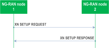
The NG-RAN node1 initiates the procedure by sending the XN SETUP REQUEST message to the candidate NG-RAN node2. The candidate NG-RAN node2 replies with the XN SETUP RESPONSE message.
The AMF Region Information IE in the XN SETUP REQUEST message shall contain a complete list of Global AMF Region IDs to which the NG-RAN node1 belongs. The AMF Region Information IE in the XN SETUP RESPONSE message shall contain a complete list of Global AMF Region IDs to which the NG-RAN node2 belongs.
The List of Served Cells NR IE and the List of Served Cells E-UTRA IE, if contained in the XN SETUP REQUEST message, shall contain a complete list of cells served by NG-RAN node1 or, if supported, a partial list of served cells together with the Partial List Indicator IE. The List of Served Cells NR IE and the List of Served Cells E-UTRA IE, if contained in the XN SETUP RESPONSE message, shall contain a complete list of cells served by NG-RAN node2 or, if supported, a partial list of served cells together with the Partial List Indicator IE.
If Supplementary Uplink is configured at the NG-RAN node1, the NG-RAN node1 shall include in the XN SETUP REQUEST message the SUL Information IE and the Supported SUL band List IE for each served cell where supplementary uplink is configured.
If Supplementary Uplink is configured at the NG-RAN node2, the candidate NG-RAN node2 shall include in the XN SETUP RESPONSE message the SUL Information IE and the Supported SUL band List IE for each served cell where supplementary uplink is configured.
If the NG-RAN node1 is an ng-eNB, it may include the Protected E-UTRA Resource Indication IE into the XN SETUP REQUEST. If the XN SETUP REQUEST sent by an ng-eNB contains the Protected E-UTRA Resource Indication IE, the receiving gNB should take this into account for cell-level resource coordination with the ng-eNB. The gNB shall consider the received Protected E-UTRA Resource Indication IE content valid until reception of a new update of the IE for the same ng-eNB.
The protected resource pattern indicated in the Protected E-UTRA Resource Indication IE is not valid in subframes indicated by the Reserved Subframes IE, as well as in the non-control region of the MBSFN subframes i.e. it is valid only in the control region therein. The size of the control region of MBSFN subframes is indicated in the Protected E-UTRA Resource Indication IE.
In case of network sharing with multiple cell ID broadcast with shared Xn-C signalling transport, as specified in TS 38.300, the XN SETUP REQUEST message and the XN SETUP RESPONSE message shall include the Interface Instance Indication IE to identify the corresponding interface instance.
If the Intended TDD DL-UL Configuration NR IE is included in the XN SETUP REQUEST or XN SETUP RESPONSE message, the receiving NG-RAN node should take this information into account for cross-link interference management and/or NR-DC power coordination with the sending NG-RAN node. The receiving NG-RAN node shall consider the received Intended TDD DL-UL Configuration NR IE content valid until reception of an update of the IE for the same cell(s).
If the TNL Configuration Info IE is contained in the XN SETUP REQUEST message, the NG-RAN node2 shall, if supported, take this IE into account for IPSec establishment.
If the TNL Configuration Info IE is contained in the XN SETUP RESPONSE message, the NG-RAN node1 shall, if supported, take this IE into account for IPSec establishment.
If the Partial List Indicator NR IE or the Partial List Indicator E-UTRA IE is set to "partial" in the XN SETUP REQUEST message the candidate NG-RAN node2 shall, if supported, assume that the List of Served Cells NR IE or the List of Served Cells E-UTRA IE in the XN SETUP REQUEST message includes a partial list of cells.
If the Partial List Indicator NR IE or the Partial List Indicator E-UTRA IE is set to "partial" in the XN SETUP RESPONSE message from the candidate NG-RAN node2, the NG-RAN node1 shall, if supported, assume that the List of Served Cells NR IE or the List of Served Cells E-UTRA IE in the XN SETUP RESPONSE message includes a partial list of cells.
If the Cell and Capacity Assistance Information NR IE or the Cell and Capacity Assistance Information E-UTRA IE is present in the XN SETUP REQUEST message the candidate NG-RAN node2 shall, if supported, use it when generating the list of NG-RAN served cell information to include in the XN SETUP RESPONSE message.
If the Cell and Capacity Assistance Information NR IE or the Cell and Capacity Assistance Information E-UTRA IE is present in the XN SETUP RESPONSE message from the candidate NG-RAN node2, the NG-RAN node1 shall, if supported, store the collected information to be used for future NG-RAN node interface management.
If the CSI-RS Transmission Indication IE is contained in the XN SETUP REQUEST message, the NG-RAN node2 shall, if supported, take this IE into account for neighbour cell's CSI-RS measurement.
If the CSI-RS Transmission Indication IE is contained in the XN SETUP RESPONSE message, the NG-RAN node1 shall, if supported, take this IE into account for neighbour cell's CSI-RS measurement.
The initiating NG-RAN node1 may include the PRACH Configuration IE (for served E-UTRA cells) or the NR Cell PRACH Configuration IE (for served NR cells) or the NPRACH Configuration IE (for served NB-IoT cells) in the XN SETUP REQUEST message. The candidate NG-RAN node2 may also include the PRACH Configuration IE (for served E-UTRA cells) or NR Cell PRACH Configuration IE (for served NR cells) or the NPRACH Configuration IE (for served NB-IoT cells) in the XN SETUP RESPONSE message. The NG-RAN node receiving the IE may use this information for RACH optimisation.
The XN SETUP REQUEST message may contain for each cell served by NG-RAN node1 NPN related broadcast information. The XN SETUP RESPONSE message may contain for each cell served by NG-RAN node2 NPN related broadcast information.
If the SFN Offset IE is included in the XN SETUP REQUEST or XN SETUP RESPONSE message, the receiving NG-RAN node shall, if supported, use this information to deduce the SFN0 time offset of the reported cell.The receiving NG-RAN node shall consider the received SFN Offset IE content valid until reception of an update of the IE for the same cell(s).
The NG-RAN node receiving the Supported MBS FSA ID List IE in the XN SETUP REQUEST message or the in XN SETUP RESPONSE message may use it according to TS 38.300.
If the Additional Measurement Timing Configuration List IE is contained in the XN SETUP REQUEST message, the NG-RAN node2 shall, if supported, take this IE into account for neighbour cell's CSI-RS measurement.
If the Additional Measurement Timing Configuration List IE is contained in the XN SETUP RESPONSE message, the NG-RAN node1 shall, if supported, take this IE into account for neighbour cell's CSI-RS measurement.
If the Local NG-RAN Node Identifier IE is present in the XN SETUP REQUEST message, the NG-RAN node2 shall, if supported, take this into account for future retrieval of the UE contexts from the NG-RAN node1.
If the Local NG-RAN Node Identifier IE is present in the XN SETUP RESPONSE message, the NG-RAN node1 shall, if supported, take this into account for future retrieval of the UE contexts from the NG-RAN node2.
If the Neighbour NG-RAN Node List IE is present in the XN SETUP REQUEST message, the NG-RAN node2 may take this into account for Local NG-RAN Node Identifier conflict detection.
If the Neighbour NG-RAN Node List IE is present in the XN SETUP RESPONSE message, the NG-RAN node1 may take this into account for Local NG-RAN Node Identifier conflict detection.
If the Served Cell Specific Info Request IE is included in the XN SETUP REQUEST message and if the NG-RAN node2 is a gNB, the NG-RAN node2 shall, if supported, include the Additional Measurement Timing Configuration List IE for the requested NR cells in the XN SETUP RESPONSE message.
If the RedCap Broadcast Information IE is included in the Served Cell Information NR IE in the XN SETUP REQUEST message or the XN SETUP RESPONSE message, the receiving NG-RAN node may use this information to determine a suitable target in case of subsequent outgoing mobility involving RedCap UEs.
If the TAI NSAG Support List IE is contained in the XN SETUP REQUEST or in the XN SETUP RESPONSE message, the receiving NG-RAN node shall, if supported, take this IE into account for slice aware cell reselection.
Interactions with other procedures:
If the NG-RAN node1 receives a XN SETUP RESPONSE message containing a Local NG-RAN Node Identifier identical to the Local NG-RAN Node Identifier included in the corresponding XN SETUP REQUEST message, the NG-RAN node1 may initiate the NG-RAN node Configuration Update procedure including in the NG-RAN NODE CONFIGURATION UPDATE message a new Local NG-RAN Node Identifier, different from the Local NG-RAN Node Identifier of each of its neighbour NG-RAN Nodes.
If the NG-RAN node1 receives a XN SETUP RESPONSE message containing a Local NG-RAN Node Identifier within the Neighbour NG-RAN Node List IE identical to the Local NG-RAN Node Identifier included in the corresponding XN SETUP REQUEST message, the NG-RAN node1 may initiate the NG-RAN node Configuration Update procedure including in the NG-RAN NODE CONFIGURATION UPDATE message a new Local NG-RAN Node Identifier, different from the Local NG-RAN Node Identifier of each of its neighbour NG-RAN Nodes.
8.4.1.3 Unsuccessful Operation p. 86
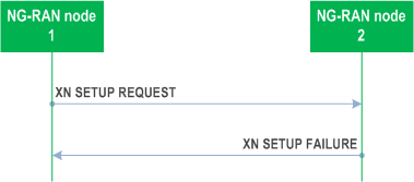
If the candidate NG-RAN node2 cannot accept the setup it shall respond with the XN SETUP FAILURE message with appropriate cause value.
If the XN SETUP FAILURE message includes the Time To Wait IE, the initiating NG-RAN node1 shall wait at least for the indicated time before reinitiating the Xn Setup procedure towards the same NG-RAN node2.
If case of network sharing with multiple Cell ID broadcast with shared Xn-C signalling transport, as specified in TS 38.300, the XN SETUP REQUEST message and the XN SETUP REQUEST FAILURE message shall include the Interface Instance Indication IE to identify the corresponding interface instance.
If the Message Oversize Notification IE is included in the XN SETUP FAILURE, the initiating node shall, if supported, deduce that the failure is due to a too large XN SETUP REQUEST message and ensure that the total number of served cells in following XN SETUP REQUEST message is equal to or lower than the value of the Maximum Cell List Size IE.
8.4.1.4 Abnormal Conditions p. 87
If the first message received for a specific TNL association is not an XN SETUP REQUEST, XN SETUP RESPONSE, or XN SETUP FAILURE message then this shall be treated as a logical error.
If the initiating NG-RAN node1 does not receive either XN SETUP RESPONSE message or XN SETUP FAILURE message, the NG-RAN node1 may reinitiate the Xn Setup procedure towards the same NG-RAN node, provided that the content of the new XN SETUP REQUEST message is identical to the content of the previously unacknowledged XN SETUP REQUEST message.
If the initiating NG-RAN node1 receives an XN SETUP REQUEST message from the peer entity on the same Xn interface:
- In case the NG-RAN node1 answers with an XN SETUP RESPONSE message and receives a subsequent Xn SETUP FAILURE message, the NG-RAN node1 shall consider the Xn interface as non operational and the procedure as unsuccessfully terminated according to sub clause 8.4.1.3.
- In case the NG-RAN node1 answers with an XN SETUP FAILURE message and receives a subsequent XN SETUP RESPONSE message, the NG-RAN node1 shall ignore the XN SETUP RESPONSE message and consider the Xn interface as non operational.
8.4.2 NG-RAN node Configuration Update p. 87
8.4.2.1 General p. 87
The purpose of the NG-RAN node Configuration Update procedure is to update application level configuration data needed for two NG-RAN nodes to interoperate correctly over the Xn-C interface.
The procedure uses non UE-associated signalling.
8.4.2.2 Successful Operation p. 87
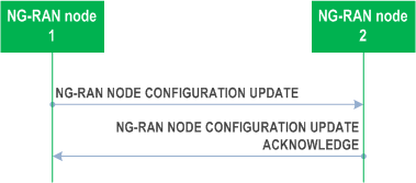
The NG-RAN node1 initiates the procedure by sending the NG-RAN NODE CONFIGURATION UPDATE message to a peer NG-RAN node2.
If Supplementary Uplink is configured at the NG-RAN node1, the NG-RAN node1 shall include in the NG-RAN NODE CONFIGURATION UPDATE message the SUL Information IE and the Supported SUL band List IE for each cell added in the Served NR Cells To Add IE and in the Served NR Cells To Modify IE.
If Supplementary Uplink is configured at the NG-RAN node2, the NG-RAN node2 shall include in the NG-RAN NODE CONFIGURATION UPDATE ACKNOWLEDGE message the SUL Information IE and the Supported SUL band List IE for each cell added in the Served NR Cells IE if any.
If the TAI Support List IE is included in the NG-RAN NODE CONFIGURATION UPDATE message, the receiving node shall replace the previously provided TAI Support List IE by the received TAI Support List IE.
If the Cell Assistance Information NR IE is present, the NG-RAN node2 shall, if supported, use it to generate the Served NR Cells IE and include the list in the NG-RAN NODE CONFIGURATION UPDATE ACKNOWLEDGE message.
If the Cell Assistance Information E-UTRA IE is present, the NG-RAN node2 shall, if supported, use it to generate the Served E-UTRA Cells IE and include the list in the NG-RAN NODE CONFIGURATION UPDATE ACKNOWLEDGE message.
If the Partial List Indicator NR IE is included in the NG-RAN NODE CONFIGURATION UPDATE ACKNOWLEDGE message and set to "partial" the NG-RAN node1 shall, if supported, assume that the Served NR Cells IE in the NG-RAN NODE CONFIGURATION UPDATE ACKNOWLEDGE message includes a partial list of NR cells.
If the Partial List Indicator E-UTRA IE is included in the NG-RAN NODE CONFIGURATION UPDATE ACKNOWLEDGE message and set to "partial" the NG-RAN node1 shall, if supported, assume that the Served E-UTRA Cells IE in the NG-RAN NODE CONFIGURATION UPDATE ACKNOWLEDGE message includes a partial list of NR cells.
If the Cell and Capacity Assistance Information NR IE is present in the NG-RAN NODE CONFIGURATION UPDATE ACKNOWLEDGE message from the candidate NG-RAN node2, the NG-RAN node1 shall, if supported, store the collected information to be used for future NG-RAN node interface management.
If the Cell and Capacity Assistance Information E-UTRA IE is present in the NG-RAN NODE CONFIGURATION UPDATE ACKNOWLEDGE message from the candidate NG-RAN node2, the NG-RAN node1 shall, if supported, store the collected information to be used for future NG-RAN node interface management.
Upon reception of the NG-RAN NODE CONFIGURATION UPDATE message, NG-RAN node2 shall update the information for NG-RAN node1 as follows:
If case of network sharing with multiple cell ID broadcast with shared Xn-C signalling transport, as specified in TS 38.300, the NG-RAN NODE CONFIGURATION UPDATE message and the NG-RAN NODE CONFIGURATION UPDATE ACKNOWLEDGE message shall include the Interface Instance Indication IE to identify the corresponding interface instance.
If the TNL Configuration Info IE is contained in the NG-RAN NODE CONFIGURATION UPDATE message, the NG-RAN node2 shall take this IE into account for IPSec establishment.
If the TNL Configuration Info IE is contained in the NG-RAN NODE CONFIGURATION UPDATE ACKNOWLEDGE message, the NG-RAN node1 shall take this IE into account for IPSec establishment.
If the CSI-RS Transmission Indication IE is contained in the NG-RAN NODE CONFIGURATION UPDATE message, the NG-RAN node2 shall take this IE into account for neighbour cell's CSI-RS measurement.
The NG-RAN NODE CONFIGURATION UPDATE message may contain for each cell served by NG-RAN node1 NPN related broadcast information. The NG-RAN NODE CONFIGURATION UPDATE ACKNOWLEDGE message may contain for each cell served by NG-RAN node2 NPN related broadcast information.
If the Additional Measurement Timing Configuration List IE is contained in the NG-RAN NODE CONFIGURATION UPDATE message, the NG-RAN node2 shall take this IE into account for neighbour cell's CSI-RS measurement.
If the Local NG-RAN Node Identifier IE is present in the NG-RAN NODE CONFIGURATION UPDATE message, the NG-RAN node2 shall, if supported, take this into account for future retrieval of the UE contexts from the NG-RAN node1.
If the Local NG-RAN Node Identifier IE is present in the NG-RAN NODE CONFIGURATION UPDATE ACKNOWLEDGE message, the NG-RAN node1 shall, if supported, take this into account for future retrieval of the UE contexts from the NG-RAN node2.
If the Neighbour NG-RAN Node List IE is present in the NG-RAN NODE CONFIGURATION UPDATE message, the NG-RAN node2 may take this into account for Local NG-RAN Node Identifier conflict detection.
If the Neighbour NG-RAN Node List IE is present in the NG-RAN NODE CONFIGURATION UPDATE ACKNOWLEDGE message, the NG-RAN node1 may take this into account for Local NG-RAN Node Identifier conflict detection.
If the Local NG-RAN Node Identifier Removal IE is present in the NG-RAN NODE CONFIGURATION UPDATE message, the NG-RAN node2 shall, if supported, discard it from its context and not use it for future retrieval of the UE contexts from the NG-RAN node1.
If the Local NG-RAN Node Identifier Removal IE is present in the NG-RAN NODE CONFIGURATION UPDATE ACKNOWLEDGE message, the NG-RAN node1 shall, if supported, discard it from its context and not use it for future retrieval of the UE contexts from the NG-RAN node2.
If the Served Cell Specific Info Request IE is included in the NG-RAN NODE CONFIGURATION UPDATE message and if the NG-RAN node2 is a gNB, the NG-RAN node2 shall, if supported, include the Additional Measurement Timing Configuration List IE for the requested NR cells in the NG-RAN NODE CONFIGURATION UPDATE ACKNOWLEDGE message.
If the TAI NSAG Support List IE is contained in the NG-RAN NODE CONFIGURATION UPDATE message, the NG-RAN node shall, if supported, take this IE into account for slice aware cell reselection.
Update of Served Cell Information NR:
If the TNL Association to Add List IE is included in the NG-RAN NODE CONFIGURATION UPDATE message, the NG-RAN node2 shall, if supported, use it to establish the TNL association(s) with the NG-RAN node1. The NG-RAN node2 shall report to the NG-RAN node1, in the NG-RAN NODE CONFIGURATION UPDATE ACKNOWLEDGE message, the successful establishment of the TNL association(s) with the NG-RAN node1 as follows:
If the Coverage Modification List IE is present in the NG-RAN NODE CONFIGURATION UPDATE message, the NG-RAN node2 may use the information in the Cell Coverage State IE to identify the cell deployment configuration enabled by the NG-RAN node1 and for configuring the mobility towards the cell(s) indicated by the Global NG-RAN Cell Identity IE, as described in TS 38.300.
If the NG-RAN node1 receives a NG-RAN NODE CONFIGURATION UPDATE ACKNOWLEDGE message containing a Local NG-RAN Node Identifier identical to the Local NG-RAN Node Identifier included in the corresponding NG-RAN NODE CONFIGURATION UPDATE message, the NG-RAN node1 may initiate the NG-RAN node Configuration Update procedure including in the NG-RAN NODE CONFIGURATION UPDATE message a new Local NG-RAN Node Identifier, different from the Local NG-RAN Node Identifier of each of its neighbour NG-RAN Nodes.
If the NG-RAN node1 receives a NG-RAN NODE CONFIGURATION UPDATE ACKNOWLEDGE message containing a Local NG-RAN Node Identifier within the Neighbour NG-RAN Node List IE identical to the Local NG-RAN Node Identifier included in the corresponding NG-RAN NODE CONFIGURATION UPDATE message, the NG-RAN node1 may initiate the NG-RAN node Configuration Update procedure including in the NG-RAN NODE CONFIGURATION UPDATE message a new Local NG-RAN Node Identifier, different from the Local NG-RAN Node Identifier of each of its neighbour NG-RAN Nodes.
- If Served Cells NR To Add IE is contained in the NG-RAN NODE CONFIGURATION UPDATE message, NG-RAN node2 shall add cell information according to the information in the Served Cell Information NR IE.
- If Served Cells NR To Modify IE is contained in the NG-RAN NODE CONFIGURATION UPDATE message, NG-RAN node2 shall modify information of cell indicated by Old NR-CGI IE according to the information in the Served Cell Information NR IE.
- When either served cell information or neighbour information of an existing served cell in NG-RAN node1 need to be updated, the whole list of neighbouring cells, if any, shall be contained in the Neighbour Information NR IE. The NG-RAN node2 shall overwrite the served cell information and the whole list of neighbour cell information for the affected served cell.
- If the Deactivation Indication IE is contained in the Served Cells NR To Modify IE, it indicates that the concerned cell was switched off to lower energy consumption.
- If Served Cells NR To Delete IE is contained in the NG-RAN NODE CONFIGURATION UPDATE message, NG-RAN node2 shall delete information of cell indicated by Old NR-CGI IE.
- If the Intended TDD DL-UL Configuration NR IE is contained in the NG-RAN NODE CONFIGURATION UPDATE message, the NG-RAN node2 should take this information into account for cross-link interference management and/or NR-DC power coordination with the NG-RAN node1. The NG-RAN node2 shall consider the received Intended TDD DL-UL Configuration NR IE content valid until reception of a new update of the IE for the same NG-RAN node2.
- If the NR Cell PRACH Configuration IE is contained in the Served Cell Information NR IE in the NG-RAN NODE CONFIGURATION UPDATE message, the NG-RAN node receiving the IE may use this information for RACH optimisation.
- If the SFN Offset IE is contained in the Served Cell Information NR IE in the NG-RAN NODE CONFIGURATION UPDATE message, the NG-RAN node receiving the IE shall, if supported, use this information to update the SFN0 time offset of the reported cell.
- If the Supported MBS FSA ID List IE is contained in the Served Cell Information NR IE in the NG-RAN NODE CONFIGURATION UPDATE message, the NG-RAN node receiving the IE may use it according to TS 38.300.
- If the RedCap Broadcast Information IE is contained in the Served Cell Information NR IE in the NG-RAN NODE CONFIGURATION UPDATE message, the NG-RAN node2 may use this information to determine a suitable target in case of subsequent outgoing mobility involving RedCap UEs.
- If Served Cells E-UTRA To Add IE is contained in the NG-RAN NODE CONFIGURATION UPDATE message, NG-RAN node2 shall add cell information according to the information in the Served Cell Information E-UTRA IE.
- If Served Cells E-UTRA To Modify IE is contained in the NG-RAN NODE CONFIGURATION UPDATE message, NG-RAN node2 shall modify information of cell indicated by Old ECGI IE according to the information in the Served Cell Information E-UTRA IE.
- When either served cell information or neighbour information of an existing served cell in NG-RAN node1 need to be updated, the whole list of neighbouring cells, if any, shall be contained in the Neighbour Information E-UTRA IE. The NG-RAN node2 shall overwrite the served cell information and the whole list of neighbour cell information for the affected served cell.
- If the Deactivation Indication IE is contained in the Served Cells E-UTRA To Modify IE, it indicates that the concerned cell was switched off to lower energy consumption.
- If the Served Cells E-UTRA To Delete IE is contained in the NG-RAN NODE CONFIGURATION UPDATE message, NG-RAN node2 shall delete information of cell indicated by Old ECGI IE.
- If the Protected E-UTRA Resource Indication IE is included into the NG-RAN NODE CONFIGURATION UPDATE (inside the Served Cell Information E-UTRA IE), the receiving gNB should take this into account for cell-level resource coordination with the ng-eNB. The gNB shall consider the received Protected E-UTRA Resource Indication IE content valid until reception of a new update of the IE for the same ng-eNB. The protected resource pattern indicated in the Protected E-UTRA Resource Indication IE is not valid in subframes indicated by the Reserved Subframes IE (contained in E-UTRA - NR CELL RESOURCE COORDINATION REQUEST messages), as well as in the non-control region of the MBSFN subframes i.e. it is valid only in the control region therein. The size of the control region of MBSFN subframes is indicated in the Protected E-UTRA Resource Indication IE.
- If the PRACH Configuration IE is contained in the Served Cell Information E-UTRA IE in the NG-RAN NODE CONFIGURATION UPDATE message, the NG-RAN node receiving the IE may use this information for RACH optimisation.
- If the NPRACH Configuration IE is contained in the Served Cell Information E-UTRA IE in the NG-RAN NODE CONFIGURATION UPDATE message, the NG-RAN node receiving the IE may use this information for RACH optimisation.
- If the SFN Offset IE is contained in Served Cell Information E-UTRA IE in the NG-RAN NODE CONFIGURATION UPDATE message, the NG-RAN node receiving the IE shall, if supported, use this information to update the SFN0 time offset of the reported cell.
- A list of successfully established TNL associations shall be included in the TNL Association Setup List IE;
- A list of TNL associations that failed to be established shall be included in the TNL Association Failed to Setup List IE.
- If AMF Region Information To Add IE is contained in the NG-RAN NODE CONFIGURATION UPDATE message, the NG-RAN node2 shall add the AMF Regions to its AMF Region List.
- If AMF Region Information To Delete IE is contained in the NG-RAN NODE CONFIGURATION UPDATE message, the NG-RAN node2 shall remove the AMF Regions from its AMF Region List.
- If the Cell Deployment Status Indicator IE is present in the Coverage Modification List IE, the NG-RAN node2 shall consider the cell deployment configuration of the cell to be modified as the next planned configuration and shall remove any planned configuration stored for this cell.
- If the Cell Deployment Status Indicator IE is present and the Cell Replacing Info IE contains non-empty cell list, the NG-RAN node2 may use this list to avoid connection or re-establishment failures during the reconfiguration, e.g. consider the cells in the list as possible alternative handover targets.
- If the Cell Deployment Status Indicator IE is not present, the NG-RAN node2 shall consider the cell deployment configuration of cell to be modified as activated and replace any previous configuration for the cells indicated in the Coverage Modification List IE.
8.4.2.3 Unsuccessful Operation p. 92
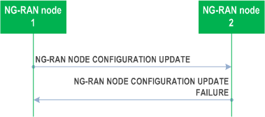
If the NG-RAN node2 cannot accept the update it shall respond with the NG-RAN NODE CONFIGURATION UPDATE FAILURE message and appropriate cause value.
If the NG-RAN NODE CONFIGURATION UPDATE FAILURE message includes the Time To Wait IE, the NG-RAN node1 shall wait at least for the indicated time before reinitiating the NG-RAN Node Configuration Update procedure towards the same NG-RAN node2. Both nodes shall continue to operate the Xn with their existing configuration data.
If case of network sharing with multiple cell ID broadcast with shared Xn-C signalling transport, as specified in TS 38.300, the NG-RAN NODE CONFIGURATION UPDATE message and the NG-RAN NODE CONFIGURATION UPDATE FAILURE message shall include the Interface Instance Indication IE to identify the corresponding interface instance.
8.4.2.4 Abnormal Conditions p. 92
If the NG-RAN node1 after initiating NG-RAN node Configuration Update procedure receives neither NG-RAN NODE CONFIGURATION UPDATE ACKNOWLEDGE message nor NG-RAN NODE CONFIGURATION UPDATE FAILURE message, the NG-RAN node1 may reinitiate the NG-RAN node Configuration Update procedure towards the same NG-RAN node2, provided that the content of the new NG-RAN NODE CONFIGURATION UPDATE message is identical to the content of the previously unacknowledged NG-RAN NODE CONFIGURATION UPDATE message.
8.4.3 Cell Activation p. 92
8.4.3.1 General p. 92
The purpose of the Cell Activation procedure is to enable an NG-RAN node to request a neighbouring NG-RAN node to switch on one or more cells, previously reported as inactive due to energy saving.
The procedure uses non UE-associated signalling.
8.4.3.2 Successful Operation p. 92
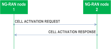
The NG-RAN node1 initiates the procedure by sending the CELL ACTIVATION REQUEST message to the peer NG-RAN node2.
Upon receipt of this message, the NG-RAN node2 should activate the cell/s indicated in the CELL ACTIVATION REQUEST message and shall indicate in the CELL ACTIVATION RESPONSE message for which cells the request was fulfilled.
If case of network sharing with multiple cell ID broadcast with shared Xn-C signalling transport, as specified in TS 38.300, the CELL ACTIVATION REQUEST message and the CELL ACTIVATION RESPONSE message shall include the Interface Instance Indication IE to identify the corresponding interface instance.
Interactions with NG-RAN Configuration Update procedure:
The NG-RAN node2 shall not send the NG-RAN CONFIGURATION UPDATE message to the NG-RAN node1 just for the reason of the cell/s indicated in the CELL ACTIVATION REQUEST message changing cell activation state, as the receipt of the CELL ACTIVATION RESPONSE message by the NG-RAN node1 is used to update the information about the activation state of NG-RAN node2 cells in the NG-RAN node1.
8.4.3.3 Unsuccessful Operation p. 93
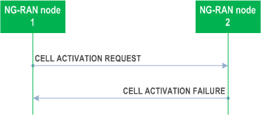
If the NG-RAN node2 cannot activate any of the cells indicated in the CELL ACTIVATION REQUEST message, it shall respond with the CELL ACTIVATION FAILURE message with an appropriate cause value.
If case of network sharing with multiple cell ID broadcast with shared Xn-C signalling transport, as specified in TS 38.300, the CELL ACTIVATION REQUEST message and the CELL ACTIVATION FAILURE message shall include the Interface Instance Indication IE to identify the corresponding interface instance.
8.4.3.4 Abnormal Conditions p. 93
Void.
![]()
![]()
![]()